
A factory V6 Toyota RAV4 uses four exhaust-feedback sensors, but they are not four identical parts. On the 3.5-liter 2GR-FE engine, Toyota uses two upstream air-fuel ratio sensors and two downstream heated oxygen sensors. Knowing the difference helps you identify the correct bank, interpret trouble codes properly, and avoid ordering the wrong replacement.
Quick Answer
A Toyota RAV4 V6 has four exhaust sensors: Bank 1 Sensor 1, Bank 2 Sensor 1, Bank 1 Sensor 2, and Bank 2 Sensor 2. The two Sensor 1 units are upstream air-fuel ratio sensors. The two Sensor 2 units are downstream heated oxygen sensors.
Key Takeaways
- This guide applies to factory 3.5-liter 2GR-FE V6 RAV4 models, primarily 2006 through 2012 in the U.S. market.
- Bank 1 is the rear bank nearest the firewall. Bank 2 is the front bank nearest the radiator.
- Sensor 1 sits before the catalytic converter. Sensor 2 sits after the converter.
- A trouble code does not prove that the named sensor has failed. Wiring, exhaust leaks, intake leaks, fuel-control faults, and catalytic-converter problems can produce similar codes.
- Toyota does not list oxygen-sensor replacement as a routine 60,000-to-100,000-mile service item in its 2012 RAV4 maintenance schedule.
Last Updated: July 13, 2026
How Many Oxygen Sensors Are in a Toyota RAV4 V6?
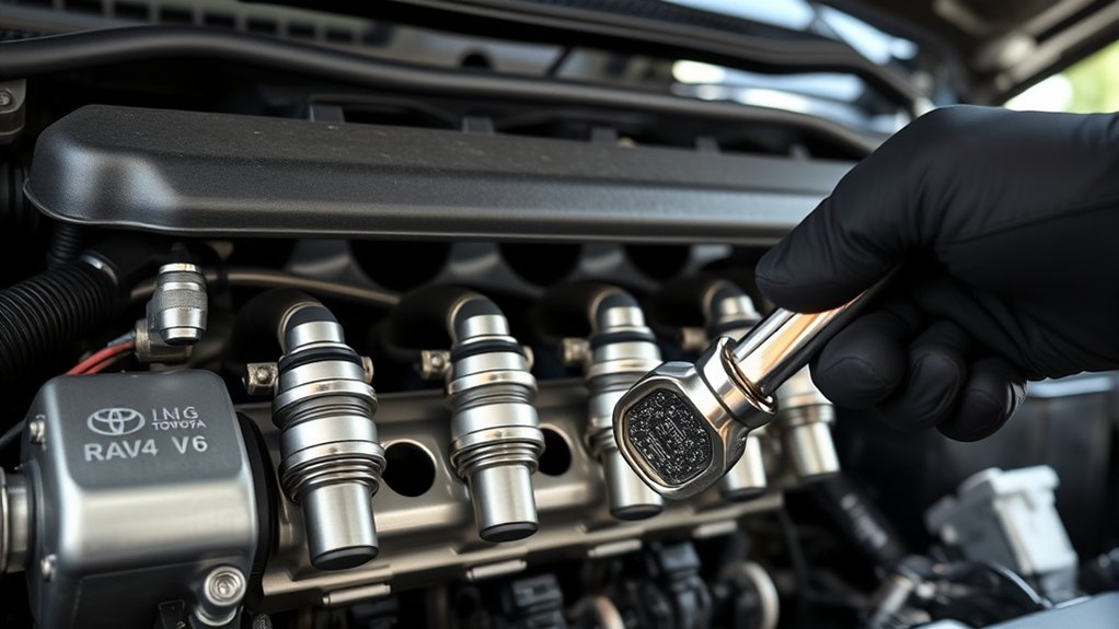
The factory V6 RAV4 has four sensors associated with its two exhaust banks. Toyota’s diagnostic terminology identifies a Sensor 1 and Sensor 2 for Bank 1, plus a Sensor 1 and Sensor 2 for Bank 2.
Owners and parts stores often group all four under the term “oxygen sensors.” Technically, the two upstream units are wide-band air-fuel ratio sensors. The two downstream units are conventional heated oxygen sensors.
Four sensors does not mean four interchangeable parts. Bank, position, connector, wire length, drivetrain, and emissions specification can change the correct part number.
RAV4 V6 Model-Year Applicability
This information applies to the factory 3.5-liter 2GR-FE V6 used in the third-generation RAV4. Toyota still listed the V6 for the 2012 RAV4. Toyota then confirmed that the previous generation’s optional V6 was discontinued for the 2013 redesign.
A four-cylinder RAV4 uses a different exhaust layout and sensor arrangement. Confirm the engine under the hood or through the vehicle identification number before ordering parts.
Where to Find Your RAV4’s Oxygen Sensors
The bank and sensor numbers tell you more than landmarks such as “front,” “rear,” “left,” or “right.” Toyota defines Bank 1 as the bank containing cylinder No. 1. On the transverse 2GR-FE installation, Bank 1 is toward the firewall and Bank 2 is toward the radiator.
| Sensor | Technical Type | General Location | Main Job |
|---|---|---|---|
| Bank 1 Sensor 1 | Air-fuel ratio sensor | Rear or firewall-side bank, before its catalytic converter | Helps the engine computer control the air-fuel mixture |
| Bank 2 Sensor 1 | Air-fuel ratio sensor | Front or radiator-side bank, before its catalytic converter | Helps the engine computer control the air-fuel mixture |
| Bank 1 Sensor 2 | Heated oxygen sensor | In the Bank 1 exhaust path after the catalytic converter | Helps monitor catalytic-converter performance |
| Bank 2 Sensor 2 | Heated oxygen sensor | In the Bank 2 exhaust path after the catalytic converter | Helps monitor catalytic-converter performance |
Exact connector locations and access routes can differ by model year, front-wheel drive or four-wheel drive configuration, and exhaust assembly. Follow the sensor wire from the exhaust body to its connector instead of pulling on the wire.
Note: You should not need to remove the interior center console for routine oxygen-sensor replacement. The sensors and their wiring belong to the exhaust and engine-control system. Some connectors may be difficult to reach from above or below, but cabin disassembly is not a normal step.
Why Upstream and Downstream Sensors Matter
Sensor Functionality Explained
The upstream A/F sensors give the engine control module detailed feedback about exhaust oxygen content. The computer uses that information with airflow, temperature, throttle, and fuel-trim data to adjust injector operation.
The downstream heated O2 sensors sit after the catalytic converters. Their readings help the onboard diagnostic system judge whether each converter is storing and processing oxygen as expected.
Toyota’s T-SB-0001-10 diagnostic bulletin treats the upstream A/F reading and downstream O2 reading as different data points. That distinction matters when diagnosing codes such as P0138, P0158, P2195, and P2197.
Importance of Sensor Placement
Sensor 1 must read exhaust before the catalytic converter changes its oxygen content. Sensor 2 must read exhaust after the converter. The computer can then compare conditions before and after catalyst treatment.
Installing the correct sensor in the wrong bank, using a conventional O2 sensor where an A/F sensor belongs, or connecting the wrong harness can leave the check engine light on even when the new part threads into the exhaust correctly.
Impact on Fuel Efficiency
A confirmed upstream A/F-sensor fault can disrupt fuel control and contribute to poor fuel economy, hesitation, rough operation, increased emissions, or an overly rich or lean mixture.
A downstream O2-sensor fault usually affects catalyst monitoring more directly than fuel control. It can illuminate the check engine light or prevent an emissions inspection from completing without causing a dramatic change in how the RAV4 drives.
Replacing a working sensor will not improve fuel economy. Correct the actual cause, which may involve an intake leak, exhaust leak, damaged harness, fuel-delivery problem, contaminated sensor, or failing catalytic converter.
Signs of Failing Oxygen Sensors

A check engine light is the most common warning, but the symptoms depend on which sensor or circuit has a problem.
- Check engine light: The engine computer may store a sensor, heater, fuel-trim, catalyst-efficiency, or circuit code.
- Reduced fuel economy: This is more likely when an upstream A/F sensor or another fuel-control problem affects mixture correction.
- Rough idle or hesitation: These symptoms can accompany an upstream feedback fault, but vacuum leaks, ignition faults, injectors, and airflow problems can produce the same behavior.
- Rich exhaust odor: An overly rich mixture may create a fuel smell, although the sensor is only one possible cause.
- Failed emissions inspection: A stored emissions code or incomplete readiness monitor can prevent a passing result.
- No noticeable driving symptom: A downstream heater or monitoring fault may turn on the light while the vehicle still feels normal.
Warning: A trouble code names the circuit or condition that failed a test. It does not automatically identify the part that must be replaced. Diagnose wiring, connectors, leaks, fuel control, and related components before buying a sensor.
How to Diagnose Oxygen Sensor Issues
Use a scan tool that can display stored codes, pending codes, freeze-frame information, fuel trims, and live sensor data. A basic reader that only erases codes may not provide enough information for a reliable diagnosis.
Diagnostic Workflow
- Record all codes before clearing anything. Save freeze-frame engine speed, load, coolant temperature, fuel trims, and sensor values.
- Confirm the named bank and position. Bank 1 is the firewall side. Bank 2 is the radiator side. Sensor 1 is upstream, and Sensor 2 is downstream.
- Inspect the wiring and connector. Look for melted insulation, stretched wires, corrosion, loose terminals, contact with the exhaust, and previous repair damage.
- Check for exhaust leaks. A leak before or near a sensor can introduce outside oxygen and distort the reading.
- Check for intake and fuel-control problems. Vacuum leaks, airflow-sensor faults, injector problems, low fuel pressure, or purge-system leaks can make a healthy A/F sensor report a lean or rich condition.
- Identify the data type. Do not interpret an upstream A/F sensor as though it were a conventional 0.1-to-0.9-volt O2 sensor.
- Compare both banks. Similar operating conditions can make a bank-to-bank comparison useful when one sensor or circuit behaves differently.
- Follow the Toyota repair procedure for the exact code. Heater, signal, circuit, response, and catalyst codes require different tests.
- Confirm the repair. Road-test the vehicle, recheck pending codes, inspect fuel trims, and verify that the fault does not return.
Common RAV4 V6 Sensor-Related Codes
| Code Example | General Meaning | Diagnostic Caution |
|---|---|---|
| P2195 or P2197 | Upstream A/F-sensor signal indicates a stuck-lean condition for Bank 1 or Bank 2 | Inspect the circuit, intake leaks, fuel delivery, exhaust leaks, and sensor response before replacement. |
| P0138 or P0158 | High-voltage condition associated with a downstream O2 circuit on Bank 1 or Bank 2 | Toyota documented cases where upstream A/F-sensor response affected the diagnosis. Do not replace the downstream sensor solely from the code description. |
| P0136 or P0156 | Downstream O2-sensor circuit malfunction for Bank 1 or Bank 2 | Check the connector, heater supply, ground, signal circuit, and exhaust condition. |
| P0420 or P0430 | Catalyst efficiency below threshold for Bank 1 or Bank 2 | The converter, exhaust leaks, misfires, fuel control, and sensor data all require evaluation. The code does not automatically mean the downstream sensor is bad. |
Pro Tip: Photograph the scan-tool screen and connector routing before disconnecting anything. Keeping the freeze-frame data and wire path makes bank identification and post-repair comparison much easier.
Replacing Oxygen Sensors: Step-by-Step Guide
You can replace an accessible RAV4 V6 sensor at home if you can identify the correct part, support the vehicle safely, and work without damaging the exhaust threads. Rear-bank access, severe corrosion, or an uncertain diagnosis can make professional service the safer choice.
At a Glance
| Time Required | About 1 to 2 hours for an accessible sensor; corrosion or rear-bank access can take longer |
| Difficulty | Intermediate |
| Tools Needed | Live-data scan tool, oxygen-sensor socket, ratchet, extensions, torque wrench, penetrating oil, safety glasses, wheel chocks, jack, and rated jack stands |
| Cost | Varies by bank, sensor position, VIN, emissions specification, part quality, and labor access |
Warning: Let the exhaust cool completely before touching a sensor. Work on a level surface, chock the wheels, and support the RAV4 with rated jack stands at approved lift points. Never work beneath a vehicle supported only by a hydraulic jack.
Tools and Parts
- Direct-fit A/F or O2 sensor verified for your VIN, engine, bank, and position
- OBD-II scan tool with live-data capability
- Slotted oxygen-sensor socket or suitable sensor wrench
- Ratchet, extensions, and possibly a breaker bar
- Torque wrench that covers the specified tightening range
- Penetrating oil for corroded threads
- Wheel chocks, jack, and rated jack stands when under-vehicle access is required
- Safety glasses and mechanic’s gloves
Replacement Steps
- Confirm the failed circuit. Record the codes, freeze-frame data, and live readings before disconnecting the battery or clearing anything.
- Verify the replacement part. Match the VIN, 2GR-FE engine, Bank 1 or Bank 2, Sensor 1 or Sensor 2, drivetrain, connector, and emissions specification. Do not rely only on thread size.
- Park and cool the vehicle. Set the parking brake, chock the wheels, remove the key, and wait until the exhaust is cold.
- Raise the RAV4 safely when needed. Use the approved lift points and place rated jack stands before going underneath.
- Locate the sensor and connector. Trace the wire to its connector. Release the locking tab without pulling on the wires.
- Apply penetrating oil if needed. Put a small amount around the sensor threads while keeping oil away from the connector and sensor tip. Allow time for it to penetrate.
- Remove the old sensor. Fit the slotted socket over the wire and loosen the sensor. Support the tool squarely to reduce the chance of damaging the exhaust bung.
- Compare the parts. Check the connector shape, wire length, protective sleeve, thread size, and sensor body before installation.
- Prepare the threads correctly. Many direct-fit sensors arrive with thread compound already applied. Do not add more unless the sensor manufacturer instructs you to do so. Keep all compound off the sensing element.
- Start the new sensor by hand. Turn it several threads before using a wrench. Hand-starting reduces the risk of cross-threading the exhaust.
- Tighten to the correct specification. Use the Toyota repair information or instructions supplied with the exact sensor. A universal torque value may not fit every part or exhaust assembly.
- Route and connect the harness. Follow the original clips and heat shields. Keep the wire away from the exhaust, steering, axle, and suspension components.
- Reconnect the battery if you disconnected it. Battery disconnection is not required for every sensor procedure, so follow the model-specific repair instructions.
- Clear codes only after completing the repair. Start the engine, listen for an exhaust leak, inspect the harness, and check live data.
- Road-test and rescan. Confirm that no pending code returns and that the relevant sensor data behaves normally.
Clearing codes or disconnecting the battery can reset emissions readiness monitors. The RAV4 may need one or more complete drive cycles before an inspection system reports the monitors as ready.
When to Hire a Mechanic
Professional help makes sense when the sensor is seized, the exhaust bung begins to distort, the rear-bank connector cannot be reached safely, the wiring requires circuit testing, or the code returns after replacement.
A technician with Toyota-compatible live data can also determine whether the problem involves the A/F sensor, downstream O2 sensor, harness, engine mixture, or catalytic converter before parts are replaced.
Frequently Asked Questions
Can I replace a RAV4 V6 oxygen sensor myself?
You can replace an accessible sensor if you have a scan tool, sensor socket, safe lifting equipment, and the correct direct-fit part. Hire a mechanic when access is restricted, the sensor is seized, or electrical testing is needed.
How often should I replace the oxygen sensors in my RAV4?
Toyota’s 2012 RAV4 maintenance schedule does not list routine oxygen-sensor replacement at a fixed mileage. Replace a sensor when proper diagnosis confirms that it or its heater circuit has failed.
Where is Bank 1 Sensor 1 on a Toyota RAV4 V6?
Bank 1 Sensor 1 is the upstream air-fuel ratio sensor on the rear engine bank nearest the firewall. It sits in the exhaust path before the Bank 1 catalytic converter.
Will a new sensor improve my RAV4’s fuel economy?
A new upstream A/F sensor may restore proper fuel control when the original sensor has genuinely failed. Replacing a working sensor will not improve mileage, and a downstream O2 sensor usually has less direct influence on fuel mixture.
Should I replace all four sensors at the same time?
No. Replace the sensor or repair the circuit that testing identifies as faulty. Replacing all four without diagnosis adds cost and can introduce wrong-part or connector-routing problems.
Can I drive with an oxygen-sensor code?
The RAV4 may remain drivable, especially with a downstream monitoring fault, but you should diagnose it promptly. A rich mixture, active misfire, flashing check engine light, severe hesitation, or strong fuel smell requires immediate attention.
Which replacement-sensor brand should I use?
Choose a genuine Toyota or reputable OE-equivalent direct-fit sensor. Verify the part by VIN, engine, bank, sensor position, drivetrain, connector, and emissions specification rather than choosing by brand name alone.
Conclusion
A Toyota RAV4 with the factory 3.5-liter V6 has four exhaust-feedback sensors: two upstream A/F sensors and two downstream heated O2 sensors. Bank 1 is toward the firewall, Bank 2 is toward the radiator, Sensor 1 is before the catalyst, and Sensor 2 is after it.
Use the bank and sensor number to identify the part, but do not replace it from the code description alone. Record the diagnostic data, inspect the circuit and exhaust, verify the sensor by VIN, and follow safe lifting and torque procedures during replacement.
Sources
- Toyota Technical Service Bulletin T-SB-0001-10 — RAV4 A/F and O2 sensor diagnostic procedures for P0138, P0158, P2195, P2197, and P0606.
- Toyota 2012 RAV4 Model Information — confirms availability of the 3.5-liter V6 for 2012.
- Toyota 2013 RAV4 World Debut — confirms discontinuation of the previous generation’s optional V6.
- Toyota 2012 RAV4 Warranty and Maintenance Guide — factory maintenance schedule and emissions-system information.
- DENSO Air/Fuel Sensor Guide — differences between wide-band A/F sensors and conventional oxygen sensors.
- DENSO O2 and A/F Sensor Troubleshooting — systematic diagnosis, sensor positioning, and live-data guidance.
