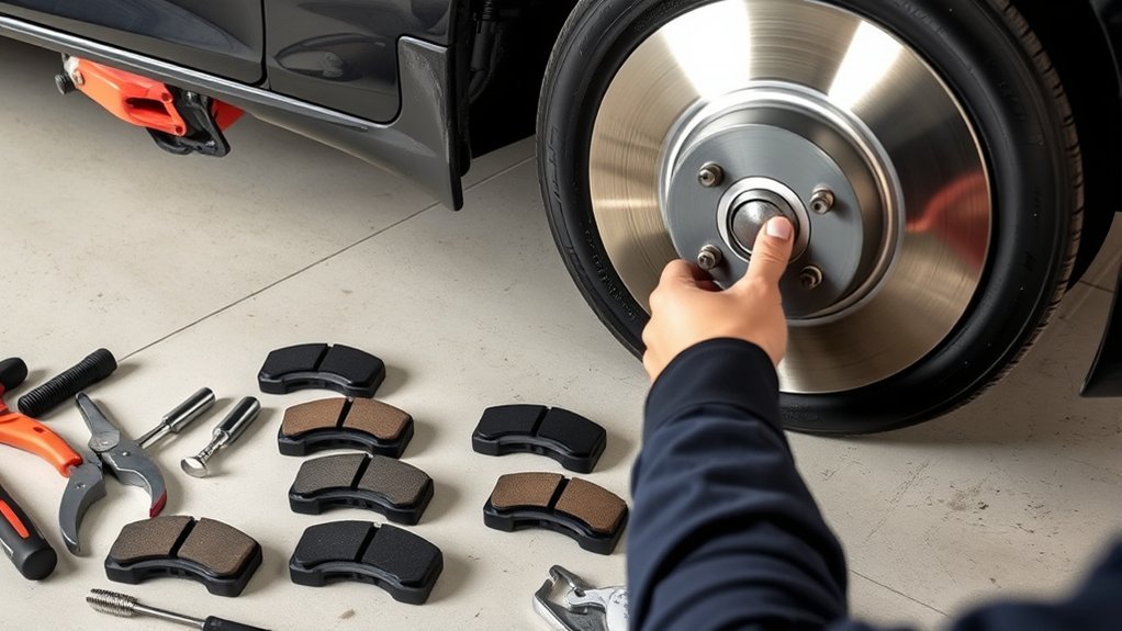
Replacing the front brake pads and rotors on a 2009 Toyota Camry can be a manageable DIY job when you have the correct parts, tools, measurements, and service specifications. This guide’s detailed mechanical sequence is intended for conventional gasoline models. The 2009 Camry Hybrid uses an electronically controlled, pump-pressurized brake system and requires Toyota’s hybrid-specific service procedure.
Last reviewed: July 13, 2026
Quick Answer
For a conventional 2009 Camry, support the car on jack stands, remove both front wheels, inspect the hydraulic parts, replace or measure both rotors, install new pads and hardware, torque each fastener correctly, pump the pedal firm, check for leaks, test at walking speed, and follow the friction manufacturer’s bedding procedure.
Key Takeaways
- Identify the vehicle by VIN and confirm whether it is a conventional gasoline Camry or Camry Hybrid before starting.
- Verify pad, rotor, and hardware fitment against the VIN, build configuration, and installed brake package.
- Never work under a car held only by a hydraulic jack; use correctly rated stands on solid, level ground.
- Do not confuse 14 mm or 17 mm socket sizes with torque values. The common non-hybrid bracket, slide-pin, and wheel fasteners use separate specifications.
- Keep brake fluid, lubricant, oil, dirty gloves, and fingerprints away from the pad and rotor friction surfaces.
- Do not move the vehicle until the pedal is firm, all fasteners are checked, the fluid is in range, and no leak or warning light is present.
At a Glance
| Time Required | About 2–4 hours for an experienced DIYer; allow a half day for a first attempt, inspection, measurement, and bedding |
| Difficulty | Intermediate and safety-critical; the Camry Hybrid requires a separate electronically controlled brake procedure |
| Tools Needed | Floor jack, jack stands, wheel chocks, metric sockets, breaker bar, torque wrench, piston-compression tool, caliper hanger, brake-dust control supplies, micrometer, and preferably a dial indicator |
| Cost | Varies by market, currency, rotor coating, pad compound, brake package, and brand; obtain current local pricing for pads, two rotors, hardware, cleaner, and lubricant |
Warning: Brake work directly affects vehicle control. Work on a level surface, chock the rear wheels, use approved lifting points and correctly rated jack stands, and wear eye protection and chemical-resistant gloves. Never rely on a hydraulic jack alone. Stop if you find leaking fluid, damaged threads, a seized piston, a cracked or swollen hose, a brake warning light, or any condition you cannot confidently diagnose.
Confirm the Camry Model and Brake System
Begin with the VIN, not only the words “2009 Camry.” Confirm the model, engine, production configuration, trim, installed brake package, and whether previous repairs have changed any components. Use Toyota’s 2009 Camry manuals page, the VIN-based parts catalog used by your supplier, and Toyota’s Technical Information System.
Before buying parts, compare the new pads and rotors with the old components or obtain dimensions from a reliable VIN-based catalog. Check rotor diameter, thickness, overall height, center bore, vent design, bolt pattern, pad shape, wear-indicator position, and included hardware.
It is also sensible to enter the VIN in the NHTSA recall lookup before service. Recall status does not normally determine pad-and-rotor fitment, but an open brake-related campaign should be addressed through the proper repair channel.
Camry Hybrid Warning: Stop if the VIN identifies a 2009 Camry Hybrid. Its brake actuator stores pressure and is controlled electronically. Do not rely on the conventional piston-compression sequence below. Use Toyota’s hybrid repair manual and its required diagnostic, pressure-release, and system-disable procedure. A technician without the required information, scan equipment, and hybrid brake training should not perform this repair.
2009 Toyota Camry Front Brake Specifications
The following table combines specifications from Toyota’s 2009 owner information with commonly listed Toyota service data for the North American conventional front brake setup. Confirm the repair-manual values against the VIN, production configuration, installed brake package, and the markings on the actual parts before applying them.
| Item | Reference Value | Important Note |
| Brake fluid | SAE J1703 or FMVSS No. 116 DOT 3 | Use clean fluid from a sealed container when fluid service is required. |
| Front pad lining wear limit | 1.0 mm (0.04 in.) | Replace sooner for uneven wear, cracking, separation, glazing, contamination, or damaged hardware. |
| Common front rotor nominal thickness | 28.0 mm (1.102 in.) | Confirm the rotor and brake package before use. |
| Common front rotor minimum thickness | 25.0 mm (0.984 in.) | Use the stricter applicable value if the replacement rotor or Toyota service data specifies one. |
| Common maximum installed rotor runout | 0.05 mm (0.002 in.) | Runout is the side-to-side wobble measured while the rotor turns on the hub. |
| Common front caliper slide-pin bolt torque | 34 N·m (25 ft-lb) | Hold the slide pin as required so its boot does not twist. |
| Common front caliper bracket bolt torque | 107 N·m (79 ft-lb) | These bolts are substantially tighter than the slide-pin bolts. |
| Wheel-nut torque | 103 N·m (76 ft-lb) | Apply to clean, dry threads and seats unless Toyota specifically directs otherwise. |
Note: A 14 mm or 17 mm socket size does not mean 14–17 N·m of torque. Tool size and tightening torque are unrelated measurements. If the VIN-specific Toyota procedure differs from the reference values above, follow the VIN-specific procedure.
Toyota’s 2009 Camry owner’s manual lists 1.0 mm (0.04 in.) as the brake-pad wear limit. Three millimetres can be used as an early planning point, but it is not the factory wear limit.
Step-by-Step Guide to Replacing Front Brake Pads and Rotors
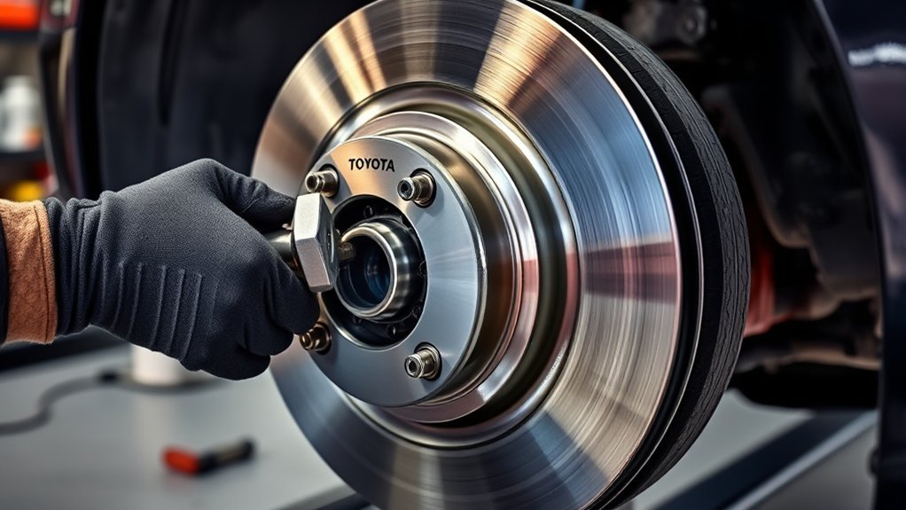
Use this sequence as the complete workflow for a conventional gasoline 2009 Camry. Read the whole procedure before lifting the vehicle so you know where each inspection, measurement, and stop-work decision occurs.
- Confirm the model and parts. Verify that the car is not a Camry Hybrid. Match the pads, rotors, clips, shims, and other hardware to the VIN and installed brake package.
- Collect the specifications. Record the applicable slide-pin, bracket, and wheel torque values, along with rotor thickness and runout limits.
- Prepare the vehicle. Park on hard, level ground, switch off the car, apply the parking brake, chock the rear wheels, and loosen the front lug nuts slightly.
- Lift and support the front. Use the approved lifting points and place the vehicle securely on correctly rated jack stands.
- Remove both front wheels. Service and inspect both sides of the axle during the same job.
- Check the reservoir. Clean around the brake-fluid cap and note the fluid level before compressing either piston.
- Remove and support the caliper. Unbolt it, hang it securely, and never let its weight pull on the flexible hose.
- Remove the pads and bracket. Record the positions of wear indicators, clips, shims, springs, and slide-pin components.
- Inspect or replace the rotors. Measure any rotor proposed for reuse and clean the hub before installing a replacement.
- Retract the piston slowly. Use an old pad and a suitable compression tool while watching the reservoir for rising fluid.
- Install new hardware and pads. Use compatible brake lubricant only at approved contact points.
- Reassemble and torque the brakes. Start every fastener by hand and tighten the bracket and slide-pin bolts to their separate specifications.
- Reinstall and torque the wheels. Start the lug nuts by hand, snug them in a crisscross sequence, lower the vehicle correctly, and apply the specified final torque.
- Restore pedal position. Pump the pedal until it is firm at a normal height, then check the fluid level and inspect for leaks.
- Test and bed the brakes. Test first at walking speed in a clear area, then follow the pad or rotor manufacturer’s bedding instructions.
Pro Tip: Photograph each side before removing the pads, shims, clips, springs, and wear indicators. Also place the removed left- and right-side parts in separate trays so their original positions remain clear.
[Amazon Products Picked for You]

PLEASE CONFIRM YOUR FITMENT: Using the Amazon Confirmed Fit bar at the top of the page or check the Product Description to confirm your vehicle fitment. This may be delivered in multiple boxes

Brake Pads Brake Rotors Replacement for 2013-2018 Lexus ES300h - [2007-2015 Lexus ES350] - 2016-2018 Lexus ES350 (Assembled in Japan & USA) - [2008-2018 Toyota Avalon] - 2007-2017 Toyota Camry

[Fitment] Lexus 2007-2018 Lexus ES350; Lexus 2013-2018 Lexus ES300H; Toyota 2007-2017 Toyota Camry; Toyota 2008-2018 Toyota Avalon
Essential Tools and Parts for Brake Replacement
Gather every required item before lifting the car. Stopping midway to find a tool can leave the vehicle exposed to contamination or make it tempting to use an unsuitable substitute.
[Amazon Products Picked for You]
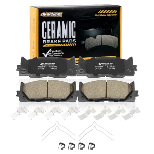
- AUTOMOTIVE REPLACEMENT BRAKE PADS FRONT : Ceramic Front Brake Pads Set Compatible with 2008-2018 Toyota Avalon,2007-2017 Toyota Camry,Compatible with 2007-2018 Lexus ES350,2013-2018 Lexus ES300h.Before purchasing, please confirm whether the product is compatible with your vehicle by using the "amazon confirmed fit" tool to confirm the compatibility of the specific model

OE REPLACEMENT: Designed and engineered to OE specifications for fit, form, and function

[PLATFORM SPECIFIC FRICTION MATERIAL} - Bosch Blue offers advanced, platform specific Ceramic friction material formulations for optimal stopping power, reduced brake fade, and long-lasting performance
Parts and Supplies
- Front brake pads that match the exact VIN and brake package
- Two matching front rotors when replacement is required
- New pad-abutment clips, shims, springs, or hardware kit as supplied or recommended
- Brake-specific lubricant compatible with the caliper, slide-pin boots, and pad hardware
- EPA-compliant dust-control supplies or appropriate brake-service HEPA equipment
- Rotor cleaner or preparation products approved by the rotor manufacturer
- Clean, lint-free towels
- SAE J1703 or FMVSS No. 116 DOT 3 brake fluid if fluid service becomes necessary
Tools and Safety Equipment
- Wheel chocks
- Floor jack with adequate capacity
- Properly rated jack stands
- Metric six-point socket and wrench set
- Breaker bar
- Torque wrench covering both the slide-pin and bracket-bolt ranges
- Brake-caliper piston-compression tool or suitable clamp
- Caliper hanger, strong wire, or purpose-made hook
- Micrometer for rotor thickness
- Dial indicator and rigid magnetic or clamp base for installed runout
- Flat washers or suitable spacers for temporarily securing the rotor with lug nuts
- Small nylon or brass brush for an already decontaminated, removed metal bracket or hub surface
- Eye protection and chemical-resistant gloves
The commonly encountered 14 mm and 17 mm fastener heads may help you select sockets, but inspect the actual fasteners before beginning. Never convert a socket size into a torque value.
Confirm Fitment and Factory Specifications
Use Toyota’s manuals and warranties portal for vehicle information. Obtain VIN-specific repair procedures, torque values, wear limits, diagnostic precautions, and brake-package details from Toyota TIS or another licensed source of Toyota factory service data.
Do not rely only on a marketplace listing that says “fits 2007–2011 Camry.” Production configuration, hybrid equipment, previous repairs, and brake options can affect the parts and procedure.
Control Brake Dust Before Disassembly
Treat all brake dust as potentially hazardous. The age or appearance of a pad does not reliably reveal what its dust contains.
Warning: Do not use compressed air, a dry rag, a dry brush, a garden hose, or an ordinary wet/dry shop vacuum on a dusty brake assembly. These methods can spread fine particles into the air or surrounding workspace.
For home work, follow the EPA’s current brake and clutch dust guidance. Use an appropriate wet-wipe method or purpose-built HEPA brake-service equipment, contain the residue, and dispose of used wipes and debris according to applicable local requirements.
After loose dust has been captured and the removed metal parts are decontaminated, a small nylon or brass brush may be used carefully on bare bracket lands or the hub face to remove corrosion. Do not brush friction material, dusty hardware, boots, hoses, or assembled components.
How to Remove the Brake Caliper for Access
Turn the steering wheel as needed to improve access, but do not place side loads on the vehicle or disturb its support. Inspect the flexible hose before moving the caliper. Replace a hose that is cracked, swollen, chafed, twisted, wet with fluid, or damaged at a fitting.
Tools Required for Removal
Use a correctly fitting six-point socket or wrench on the slide-pin bolts. Keep the caliper hanger within reach so the caliper can be supported immediately after removal.
The piston-compression tool is used later. Do not force the piston back with a screwdriver against a new rotor, the piston boot, or an exposed friction surface.
Caliper Separation Technique
- Confirm that the vehicle remains stable on both stands.
- Remove the caliper slide-pin bolts while supporting the caliper body.
- Rock the caliper gently to create clearance from the worn pads.
- If more clearance is necessary, apply controlled pressure against an old pad instead of gouging the rotor or piston boot.
- Lift the caliper from the bracket.
- Hang it from a solid suspension point with a suitable hook or wire.
- Check that the hose is not supporting the caliper, twisted, kinked, stretched, or sharply bent.
Safety Precautions During Removal
- Confirm that both jack stands remain stable before applying force to a stubborn fastener.
- Keep your body out from under unsupported brake or suspension components.
- Do not open the bleeder screw unless the selected service procedure requires it.
- Do not press the brake pedal while a caliper is removed.
- Keep petroleum grease away from brake rubber, pads, and rotors.
- Stop if the hose, bleeder, piston boot, mounting threads, bracket, or caliper body is damaged.
Note: Removing the reservoir cap does not relieve pressure in the brake lines. Clean around the cap and monitor the level so returning fluid does not overflow while the piston is compressed.
Removing Old Brake Pads and Rotors
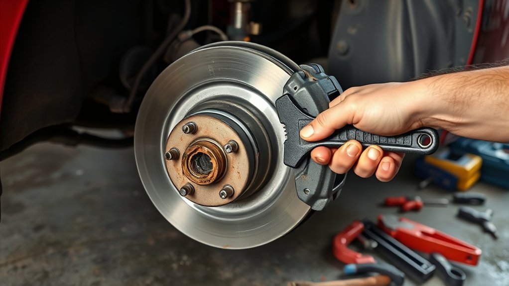
Remove the pads from the bracket and compare their thickness and wear pattern. Uneven inner-to-outer or left-to-right wear can indicate seized slide pins, a sticking piston, a restricted hose, incorrect hardware, rotor misalignment, or a mounting problem.
Remove the caliper bracket to gain access to the rotor. Bracket bolts are much tighter than slide-pin bolts, so keep the socket fully seated and position the breaker bar so a sudden release does not destabilize the vehicle or injure your hand.
After the bracket is removed, slide the rotor from the hub. If corrosion holds it in place, use the rotor’s threaded extraction holes when provided and follow the rotor or Toyota procedure. Tighten suitable extraction bolts evenly. Do not strike the wheel studs, bearing, or hub, and do not hit the rotor so aggressively that the vehicle moves on its stands.
Inspect the Removed Components
- Pads: Check for taper wear, cracks, glazing, crumbling, separation, oil, grease, or brake-fluid contamination.
- Rotor: Check for deep scoring, cracks, heavy edge lips, severe rust, blue heat spots, and thickness below specification.
- Slide pins: Confirm that each pin is straight, moves smoothly, and has an intact sealing boot.
- Caliper piston: Look for fluid leakage, corrosion, a torn boot, tilting, or uneven movement.
- Brake hose: Inspect for swelling, cracks, chafing, wetness, damaged fittings, and twisting.
- Bracket: Check the pad-contact lands, hardware seats, threads, and casting for deep corrosion, distortion, or cracks.
- Hub: Check for rust, raised debris, damaged studs, and bearing looseness that could prevent the rotor from sitting flat.
Replace a deeply corroded, cracked, or distorted bracket. Do not grind away enough material to change the fit of the abutment clips or allow the pads to rattle.
Preparing the New Rotor for Installation
Compare the new and old rotors before installation. Check diameter, overall height, center bore, bolt pattern, nominal thickness, vent design, and any left- or right-side marking.
Clean Oil Coating Removal
Follow the rotor manufacturer’s preparation instructions. Some uncoated rotors arrive with protective oil that must be removed. Other rotors have a permanent coating intended to remain in place and may not require solvent cleaning.
When cleaning is required:
- Work in a ventilated area away from flames, sparks, and hot surfaces.
- Read and follow the cleaner’s label and safety instructions.
- Apply the approved product to both friction faces.
- Wipe with a clean, lint-free towel.
- Repeat until the towel shows no oily residue.
- Allow the rotor to dry fully.
- Handle the rotor by its edges or hat afterward.
Proper Rotor Alignment Check
Clean the wheel-hub face until the rotor can sit flat. A small patch of rust or debris trapped between the hub and rotor can create lateral runout, which is a side-to-side wobble that may later contribute to uneven friction transfer or pedal pulsation.
Install the rotor flush against the hub. To hold it in the same seated position used during measurement, install several lug nuts backward only when their flat side can bear on suitable flat washers or spacers without damaging the rotor or nut. Tighten them evenly enough to seat the rotor; do not place a tapered lug-nut seat directly against a flat rotor surface.
Plain replacement rotors are often non-directional. Directional-vane, drilled, or slotted rotors may have arrows or left/right labels. Follow the rotor manufacturer’s instructions rather than assuming that every slot or hole must lean in a particular direction.
Measure a Rotor Before Reusing It
Measure rotor thickness at several evenly spaced locations around the friction ring with a micrometer. Keep the measuring faces away from the outer rust lip. Record the lowest reading and compare it with the applicable minimum-thickness specification.
Replace both front rotors when either rotor is below specification, cracked, severely scored, heat-damaged, or unable to meet the required surface and runout limits. Replacing rotors as an axle pair supports consistent friction and heat capacity from side to side.
Check Installed Rotor Runout
- Clean the hub and rotor mounting faces completely.
- Install the rotor and hold it flat with suitable spacers and evenly tightened lug nuts.
- Mount the dial indicator rigidly to a nonmoving suspension or steering component.
- Position its tip squarely against the rotor face near the outer friction area without touching the edge.
- Zero the indicator and rotate the rotor slowly through one full revolution.
- Record the total movement and compare it with the applicable limit.
- If runout is excessive, remove the rotor, recheck the hub for debris or damage, rotate the rotor to another stud position, reinstall it, and measure again.
- If the reading remains excessive, inspect the rotor, hub, bearing, and mounting condition before continuing.
Do not assume that a new rotor automatically has acceptable installed runout. The rotor, hub face, wheel-bearing condition, and wheel-fastener clamping all affect the final reading.
Techniques for Properly Installing New Brake Pads
Compress the caliper piston slowly before fitting the new pads. Place an old pad across the piston face so the compression tool applies even pressure.
- Clean around the brake-fluid reservoir cap.
- Check whether the fluid is already near the maximum mark.
- If overflow is likely, remove a small amount with a clean, fluid-safe suction tool reserved for brake fluid.
- Compress the piston gradually while watching the reservoir.
- Keep the piston square in its bore.
- Stop if it binds, tilts, leaks, damages the boot, or requires abnormal force.
A piston that will not retract smoothly may indicate corrosion, a seized caliper, or a restricted brake hose. Excessive force can hide the fault or damage the component; it is not a valid repair.
Install new abutment clips when they are supplied or recommended. Compare their shape and orientation with the removed hardware, then seat each clip completely in the cleaned bracket.
Apply a very thin film of compatible brake lubricant only where the pad ears contact approved metal surfaces. Follow the pad and caliper manufacturer’s instructions for any shims, backing plates, springs, or anti-noise treatments.
- Do not put lubricant on the pad friction material.
- Do not put lubricant on either rotor face.
- Do not coat rubber boots with an incompatible petroleum product.
- Do not use copper grease unless the component and lubricant manufacturers approve it.
- Do not reuse damaged, distorted, loose, or badly corroded clips.
Install the pads in the correct inner and outer positions. Place wear indicators, shims, springs, and retaining features in the same required orientation on both sides.
Properly Lubricating Brake Components to Prevent Noise
Brake lubricant should allow the intended parts to move while remaining completely separated from the friction surfaces. A light film is enough; excess lubricant can migrate as the brakes heat up.
Where Lubricant May Be Used
- Clean slide-pin surfaces when the lubricant is specified and compatible with the rubber boots
- Approved pad-ear contact points on the bracket
- Approved metal-to-metal shim contact areas when required by the pad manufacturer
Where Lubricant Must Not Be Used
- Rotor friction faces
- Pad friction material
- Wheel studs, lug-nut threads, or tapered seats unless Toyota explicitly directs otherwise
- Rubber parts unless the lubricant is approved for that material
- Threaded brake fasteners unless the Toyota procedure specifies a lubricant, locking compound, or other treatment
Remove old, dirty grease before applying a light, even film of fresh lubricant. Replace torn slide-pin boots and make sure each boot seats correctly without trapping or twisting.
Best Practices for Reattaching the Brake Caliper
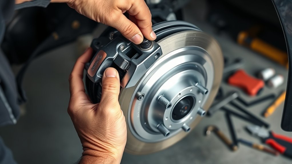
Position the caliper over the new pads without forcing it. A piston that has been compressed correctly should provide enough clearance for the caliper to fit over the assembled pads.
- Confirm that every clip, shim, pad, spring, and boot is fully seated.
- Check that the flexible hose follows its natural path and is not twisted.
- Position the caliper bracket and start both bracket bolts by hand.
- Tighten the common non-hybrid bracket bolts to 107 N·m (79 ft-lb), unless the VIN-specific Toyota procedure specifies a different value.
- Position the caliper over the pads without pinching a boot.
- Start the slide-pin bolts by hand.
- Hold each slide pin as required so it and its boot do not rotate.
- Tighten the common non-hybrid slide-pin bolts to 34 N·m (25 ft-lb), unless the VIN-specific procedure differs.
- Confirm that the caliper can slide as designed and that no boot is pinched or torn.
- Repeat the complete inspection and assembly on the opposite side.
Warning: Stop if a fastener will not start by hand, fails to tighten normally, or shows damaged threads. Do not compensate for a damaged bracket, pin, knuckle, or bolt by overtightening it.
Reinstall the Wheels
Clean the wheel and hub mating surfaces without coating them with grease. Install each wheel and start every lug nut by hand. Snug the nuts in a crisscross pattern while the wheel is seated against the hub.
Lower the vehicle according to the approved lifting procedure and tighten the lug nuts in a crisscross pattern to 103 N·m (76 ft-lb). Pull smoothly on the torque wrench and stop at its indication. Do not lubricate the studs, threads, or tapered seats unless the applicable Toyota procedure specifically requires it.
How to Test Your Brake Replacement for Safety
Complete all stationary checks before moving the car. Immediately after installation, the pedal may travel unusually far because the pistons and pads have not yet returned to their normal operating positions.
Inspect Brake Fluid Levels
Check the reservoir after both calipers are assembled and the pedal has been pumped firm. The fluid must remain between the marked minimum and maximum levels.
Use only the specified fluid. Do not automatically top up a low reservoir without looking for the reason. A falling level can accompany normal pad wear, but an external leak, hydraulic fault, or repeated need for fluid requires diagnosis.
Brake fluid can damage paint. Prevent spills and clean any spill immediately using the method recommended by the vehicle and fluid manufacturers.
Conduct the Brake Pedal Test
- With the engine off, press the brake pedal slowly several times.
- Continue until the pedal becomes firm at a normal height.
- Hold steady pressure and confirm that the pedal does not continue sinking.
- Inspect both calipers, hoses, bleeders, fittings, and the area under the car for fluid.
- Confirm that no tool, hanger, spacer, or temporary rotor-retaining hardware remains installed.
- Start the engine and confirm normal power-assist operation.
- Check that the brake and ABS warning lights complete their normal self-check and do not remain illuminated.
Do not shift into gear if the pedal remains soft, travels close to the floor, slowly sinks, cannot become firm, or changes while held. Reinspect the installation and obtain professional help if the cause is not immediately clear.
Pre-Drive Safety Checklist
- Both caliper brackets and both calipers are fully installed and torqued.
- All slide-pin boots are seated and neither brake hose is twisted.
- Both wheels are installed and the lug nuts are torqued in a crisscross pattern.
- The pedal is firm at a normal height with the engine running.
- The fluid is within the reservoir’s marked range.
- No fluid leak is visible.
- No brake or ABS warning remains on.
- The parking area and intended test path are clear.
Monitor for Abnormal Noises and Behavior
Conduct the first test in a clear, flat area at walking speed. Confirm that the car stops straight and that pedal response remains consistent. Increase speed gradually only after the first checks succeed.
- Grinding: Stop immediately and check pad orientation, missing friction material, misplaced hardware, or metal contact.
- Heavy pulling: Check for a seized caliper, restricted hose, contamination, unequal assembly, or a tire-related problem.
- Pedal pulsation: Check rotor seating, hub rust, installed runout, wheel torque, and rotor condition.
- Clicking or rattling: Inspect clips, springs, pads, bracket bolts, slide-pin bolts, and wheel fasteners.
- Smoke or burning odor: Stop and check for a dragging brake, contamination, incorrect hardware, or overheating.
- Soft or sinking pedal: Do not continue driving until the hydraulic fault is found.
- Brake or ABS warning light: Stop the test and diagnose the system before normal driving.
Bed the New Pads and Rotors
Follow the bedding procedure supplied by the pad or rotor manufacturer. Bedding creates a controlled friction-material transfer layer and helps stabilize braking performance.
No universal “30-30-30” method applies to every pad compound. Manufacturers may specify different speeds, stop counts, pedal pressure, cooling periods, and temperature cycles.
During bedding:
- Use a safe, legal road with enough space and no traffic close behind.
- Avoid triggering ABS unless the bedding instructions specifically require a hard stop.
- Do not remain stopped with the pedal clamped firmly after a high-temperature braking cycle unless necessary for safety.
- Allow the brakes to cool for the specified time and distance.
- Recheck for unequal heat, pulling, leakage, warning lights, odors, or abnormal noise afterward.
When Is Brake Bleeding Required?
A routine pad-and-rotor replacement normally does not require bleeding when the hydraulic system remains closed and the pedal becomes firm. Bleeding may be required when a caliper, hose, line, fitting, or bleeder has been opened, when the reservoir has run too low, or when air has entered the system.
Stop and diagnose the system if the pedal remains spongy. Repeated driving will not safely remove trapped air, repair a leak, or restore a failed hydraulic component.
Top Mistakes to Avoid When Replacing Your Brakes
- Using the wrong procedure: Do not apply the conventional sequence to a Camry Hybrid.
- Using the wrong parts: Verify fitment with the VIN and compare each replacement component before installation.
- Relying on a jack alone: Always use correctly rated stands on solid, level ground.
- Spreading brake dust: Do not use compressed air, dry brushing, dry rags, or an ordinary shop vacuum.
- Letting the caliper hang by its hose: Support it with a suitable hanger.
- Forcing a stuck piston: Binding or leakage can indicate a failed caliper or restricted hose.
- Skipping rotor measurements: Appearance alone does not confirm thickness, variation, or installed runout.
- Failing to clean the hub: Debris behind the rotor can create runout and later pulsation.
- Contaminating friction surfaces: Keep grease, brake fluid, oil, dirty gloves, and fingerprints away from pads and rotors.
- Applying too much lubricant: Use only a thin film at approved contact points.
- Installing hardware incorrectly: Match the inner and outer pads, indicators, clips, springs, and shims to their required positions.
- Guessing torque values: Use separate specifications for bracket bolts, slide-pin bolts, and wheel nuts.
- Failing to pump the pedal: The vehicle may have little braking on the first application.
- Skipping bedding: Follow the friction manufacturer’s procedure after all stationary checks pass.
- Ignoring unequal heat or pulling: Stop and inspect the system before normal driving.
Troubleshooting After the Brake Job
| Symptom | Possible Causes | Action |
| Soft or sinking pedal | Leak, air in the system, damaged hose, incorrect assembly, or hydraulic fault | Do not drive. Inspect and repair the fault or use a qualified technician. |
| Vehicle pulls during braking | Sticking caliper, restricted hose, contamination, unequal installation, or tire condition | Compare both sides and correct the fault before normal driving. |
| One wheel becomes much hotter | Dragging pads, seized slide pin, piston problem, restricted hose, or misinstalled hardware | Stop driving and inspect the affected brake after it cools safely. |
| Pedal pulsation | Rotor runout, hub debris, uneven wheel torque, bearing play, or thickness variation | Measure installed runout, inspect the hub and bearing, and verify wheel torque. |
| Clicking or rattling | Loose fastener, incorrect pad fit, missing clip or spring, or loose wheel hardware | Stop and inspect the complete installation before further testing. |
| Brake or ABS warning remains on | Low fluid, damaged wiring or sensor, hydraulic fault, or electronically detected brake-system problem | Do not continue the road test. Check the fluid and visible work, then obtain proper diagnostic service. |
[Amazon Products Picked for You]

[High-Quality Materials]: Caliper pin dust covers are made of high-quality rubber, making them sturdy, durable, resistant to wear and deformation, and providing excellent sealing for long-term use.

【Compatibility】: This brake caliper pins bushing kit is compatible with Cadillac 2008-2013 CTS, Lexus 2010-2012 HS250h, Scion 2011-2015 tC and xB (2008-2015 models), and Toyota 2010-2017 Prius. For more models, please refer to the product details

【Applicable Vehicle Models】Our brake caliper pin dust cover kit is compatible with Honda Civic (2001-2023), Chevrolet Malibu (2004-2012), Pontiac G5 (2007-2010), and many other cars and trucks. Please refer to the product details or check your vehicle specifications before purchasing to ensure a perfect match
Related Guides
Frequently Asked Questions
How do you change the front brake pads on a 2009 Toyota Camry?
On a conventional gasoline model, secure the vehicle on jack stands, remove both front wheels, support each caliper, remove the old pads, inspect the rotors and hydraulic parts, compress the pistons slowly, install new hardware and pads, torque the fasteners, reinstall the wheels, pump the pedal firm, check for leaks, test at low speed, and complete the specified bedding procedure.
Does the same procedure apply to a 2009 Camry Hybrid?
No. The Camry Hybrid has an electronically controlled, pump-pressurized brake system. Use Toyota’s hybrid-specific repair manual and required diagnostic and system-disable procedure. Do not begin the work without the correct information, equipment, and training.
What are the common front brake torque specifications?
For the common North American conventional setup, the front slide-pin bolts are commonly listed at 34 N·m or 25 ft-lb, the bracket bolts at 107 N·m or 79 ft-lb, and the wheel nuts at 103 N·m or 76 ft-lb. Confirm the VIN-specific Toyota service data before use.
What is the 30-30-30 rule for brakes?
There is no universal 30-30-30 maintenance or bedding rule for all brake pads. The phrase may describe repeated stops and cooling periods, but the required speeds, stop count, pressure, and cooling time depend on the friction material. Follow the instructions supplied with the pads and rotors.
At what thickness should the brake pads be replaced?
Toyota lists 1.0 mm or 0.04 inch as the 2009 Camry pad-lining wear limit. About 3 mm is often used as an early point to plan service, not as the factory limit. Replace pads sooner if they are cracked, contaminated, separating, glazed, or wearing unevenly.
Do the rotors need to be replaced whenever the pads are changed?
Not automatically. A reused rotor must remain above minimum thickness and meet the applicable limits for installed runout, thickness variation, surface condition, cracking, scoring, and heat damage. Replace the front rotors as a pair when either side fails inspection or specification.
Can you replace the pads or rotor on only one front wheel?
Front pads should be replaced as a complete axle set. When rotor replacement is required, replace both front rotors so the two sides have comparable friction surfaces and heat capacity. Inspect both calipers and hoses even when the original symptom appeared on only one side.
Do you need to bleed the brakes after changing pads and rotors?
Usually not when the hydraulic system remains closed and the pedal becomes firm. Bleeding may be required if a caliper, hose, line, fitting, or bleeder was opened, the reservoir ran too low, or air entered the system. Do not drive with a soft or sinking pedal.
What are the most common mistakes when changing brake pads?
Common mistakes include using the wrong model procedure or parts, relying on a jack alone, spreading brake dust, hanging the caliper by its hose, forcing a seized piston, contaminating friction surfaces, skipping rotor measurements, installing hardware incorrectly, guessing torque values, failing to pump the pedal, and skipping the required bedding procedure.
Conclusion
A successful 2009 Toyota Camry front brake replacement depends on identifying the correct vehicle, using compatible parts, controlling brake dust, inspecting the hydraulic components, measuring the rotors, and applying the correct torque to every fastener. The detailed conventional procedure must not be substituted for the Camry Hybrid’s electronically controlled brake-service process.
Before driving, verify the bracket, caliper, and wheel fasteners; confirm that both hoses and all boots are correctly positioned; pump the pedal until firm; check the fluid level; inspect for leaks; and confirm that no brake or ABS warning remains on. Begin with a walking-speed test and stop immediately for a soft pedal, pulling, grinding, abnormal heat, smoke, leakage, or a warning light.
Use a qualified technician if a piston binds, fluid leaks, a hose is damaged, threads are compromised, runout cannot be corrected, the pedal remains abnormal, or the required VIN-specific procedure cannot be confirmed.
Sources
- 2009 Toyota Camry Owner’s Manual — wheel-nut torque, brake-fluid specification, reservoir guidance, and brake-pad wear limit
- 2009 Toyota Camry Hybrid Owner’s Manual — electronically controlled brake and pressurized brake-actuator information
- Toyota Technical Information System — factory repair manuals, diagnostic procedures, service information, wear limits, and VIN-specific specifications
- U.S. Environmental Protection Agency Brake and Clutch Guidance — brake-dust precautions and recommended practices for home mechanics
- OSHA 29 CFR 1910.1001 Appendix F — occupational engineering controls and work practices for brake and clutch inspection and repair
- NHTSA Recall Lookup — official VIN-based search for unrepaired vehicle safety recalls
