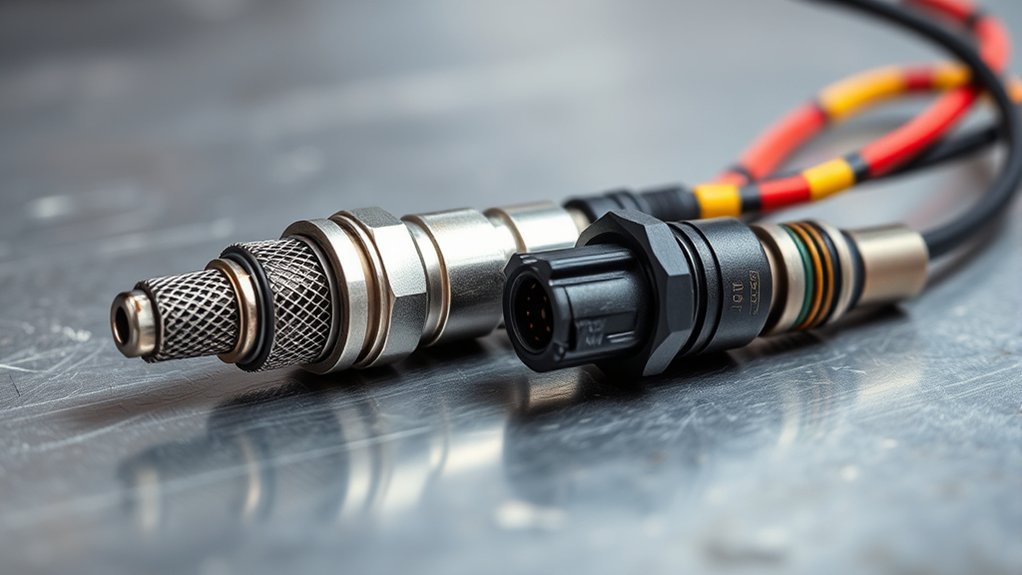
Your Toyota Camry may use both an air-fuel ratio sensor and a conventional oxygen sensor, but they perform different jobs and are not interchangeable. The upstream sensor usually helps the engine computer correct fuel delivery, while the downstream sensor usually watches catalytic-converter operation. The exact sensor count, type, bank, and position depend on the Camry’s year, engine, hybrid system, exhaust layout, and emissions certification.
Quick Answer
A Toyota Camry air-fuel ratio sensor is normally a wide-range upstream sensor used for precise fuel-control feedback. A conventional narrowband oxygen sensor often sits downstream and helps monitor the catalytic converter. They use different signal strategies and calibrations, so match replacements by VIN, engine, bank, position, connector, and part number.
Key Takeaways
- A wide-range air-fuel ratio sensor and a conventional narrowband oxygen sensor measure exhaust oxygen differently.
- Sensor 1 is normally upstream of the catalytic converter, while Sensor 2 is normally downstream.
- A trouble code identifies a monitored circuit or operating problem; it does not automatically prove that the sensor must be replaced.
- Do not judge a Toyota A/F sensor by expecting the 0.1-to-0.9-volt switching pattern of a conventional O2 sensor.
- Correct intake leaks, exhaust leaks, misfires, fuel faults, and contamination sources before condemning or replacing a sensor.
- Use Toyota service information and your VIN to confirm the correct part, scan-data item, test method, wiring diagram, and torque specification.
At a Glance
| Time Required | Plan about 30 to 90 minutes for an initial scan, visual inspection, and basic live-data review. Replacement may take about 30 minutes on an accessible sensor or several hours when access is restricted, threads are seized, or circuit diagnosis is required. These are planning estimates, not Toyota labor times. |
| Difficulty | Moderate. Seized threads, restricted access, wiring faults, hybrid-component interference, or the need for Toyota active tests can require professional equipment. |
| Tools Needed | OBD-II scan tool with live data, Toyota wiring and repair information, basic hand tools, oxygen-sensor socket, torque wrench, digital multimeter when specified, and approved lifting equipment when underside access is required |
| Cost | Varies widely by model year, engine, sensor position, part quality, accessibility, exhaust condition, diagnostic time, and local labor rates |
Understanding the Differences Between Oxygen and Air-Fuel Ratio Sensors
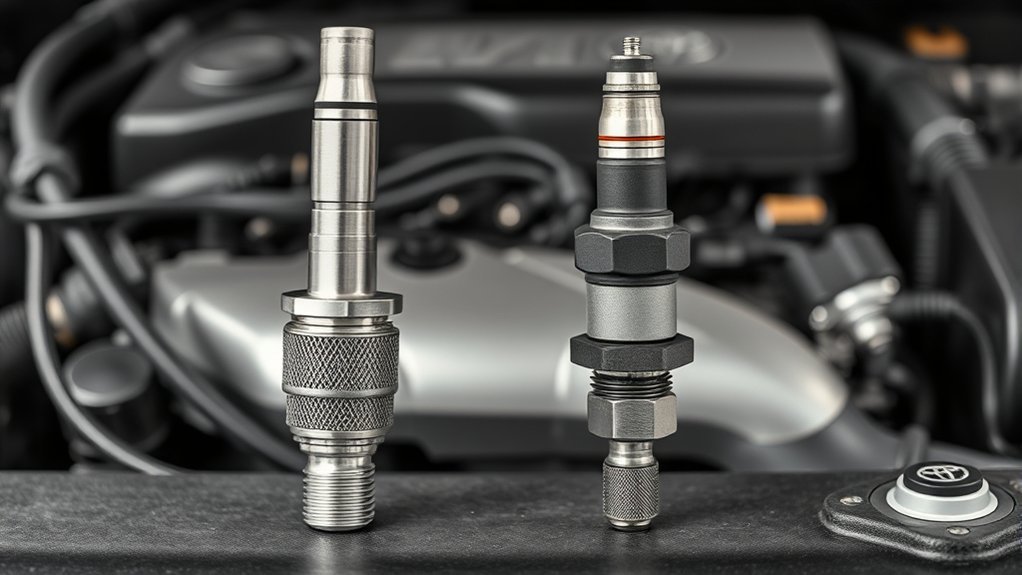
Both components detect oxygen in the exhaust stream, so both may be described broadly as oxygen or lambda sensors. Toyota commonly uses the term air-fuel ratio sensor for a wide-range upstream device and oxygen sensor for a conventional narrowband or switching device. Toyota’s parts catalog also lists Air Fuel Ratio Sensor and Oxygen Sensor as separate product types.
A heated narrowband zirconia sensor normally changes voltage sharply as the exhaust moves from lean to rich. Its signal is useful close to the stoichiometric switching point, but it does not report a broad range of mixture strength with the same detail as a wide-range sensor.
A wide-range A/F sensor uses a more complex sensing element, heater, pump cell, and control circuit. The engine control module interprets the sensor’s pump-current response to determine whether combustion is richer or leaner than the commanded mixture. The technical basis is described in SAE Technical Paper 920234, which distinguishes proportional wide-range sensing from conventional stoichiometric-point detection.
| Feature | Air-Fuel Ratio Sensor | Conventional O2 Sensor |
|---|---|---|
| Typical Camry position | Upstream of the catalytic converter | Often downstream of the catalytic converter |
| Main job | Provides broad mixture feedback for fuel correction | Reports rich-or-lean switching and may monitor catalyst operation |
| Signal behavior | Wide-range response interpreted through a pump-current and control circuit | Nonlinear voltage that changes sharply near stoichiometric operation |
| Useful scan data | A/F sensor current, equivalence ratio, lambda, or a manufacturer-specific processed value | Switching voltage, rich/lean status, and downstream catalyst-monitoring pattern |
| Interchangeable? | No | No |
Note: A connector that fits does not prove that a sensor has the correct heater resistance, calibration, signal strategy, or wire assignment. Confirm the Toyota part number or a verified direct-fit equivalent for the exact VIN, engine, emissions specification, bank, and position.
How to Read Toyota Air-Fuel Ratio Sensor Data
Do not look for one universal “good voltage” on a Toyota A/F sensor. Depending on the vehicle and scan tool, the ECM may report pump current, lambda, equivalence ratio, or a processed voltage-like data item. Some Toyota applications and scan tools show a value near 3.3 volts around stoichiometric operation, but this is not a universal raw sensor-output specification.
A displayed value can also be scaled differently by an aftermarket scan tool. Use the data-item name, units, expected direction of change, and test limits in Toyota service information. Do not assume that a number displayed as volts should appear as the same voltage when back-probing a terminal.
Warning: Do not apply battery voltage, a powered test light, or an ohmmeter to A/F sensor signal or pump-current terminals unless the Toyota test procedure specifically requires it. The wrong test connection can damage the sensor or ECM circuit.
Where Are the Sensors Located on a Toyota Camry?
OBD bank-and-sensor designations generally identify a sensor’s position in the engine and exhaust system:
- Sensor 1 is normally the upstream sensor located before the catalytic converter for that bank. On many Camrys, it is an A/F sensor used for fuel-control feedback.
- Sensor 2 is normally downstream of the monitored catalytic converter. It commonly helps the engine computer evaluate catalyst performance.
- Bank 1 is the cylinder bank containing cylinder number one.
- Bank 2 exists only when the engine has a second cylinder bank, such as on a V6.
An inline four-cylinder engine has one cylinder bank, while a V6 has two. A Camry exhaust system can also include more than one converter or monitored exhaust section. Follow the exhaust path and use a Toyota diagram rather than identifying a sensor only by how it looks or which one is easiest to see.
Pro Tip: Before unplugging anything, label the sensor as B1S1, B1S2, B2S1, or B2S2 and photograph its connector routing. This reduces the chance of testing or replacing the wrong position.
How Sensors Support Fuel Control and Emissions Monitoring
The engine control module, or ECM, controls the fuel injectors. It uses the upstream A/F or oxygen-sensor signal along with mass-airflow data, engine temperature, throttle position, load, engine speed, and other inputs.
During closed-loop operation, the ECM adjusts fuel delivery to keep combustion close to lambda 1. For gasoline, this is commonly described as about 14.7 parts air to one part fuel by mass. Bosch gives 14.66:1 in its lambda-sensor explanation, but the exact stoichiometric mass ratio varies with the fuel blend.
Operation close to lambda 1 gives a three-way catalytic converter suitable conditions to reduce hydrocarbons, carbon monoxide, and nitrogen oxides. A downstream sensor then helps the OBD system determine whether the converter is storing and processing oxygen as expected.
For diagnosis, the useful target is the manufacturer’s expected lambda, current, voltage, fuel-trim, and response pattern—not one universal sensor number.
A slow, biased, contaminated, disconnected, or electrically faulty sensor can affect fuel corrections or catalyst monitoring. Similar data can also come from an intake leak, exhaust leak, misfire, fuel-delivery problem, inaccurate airflow measurement, or damaged harness.
How Many Oxygen Sensors Does a Toyota Camry Use?
The exact number varies. Many four-cylinder Camrys use one upstream air-fuel ratio sensor and one downstream oxygen sensor. V6 models may use separate upstream sensors for each bank and additional downstream sensors. Hybrid models, different exhaust layouts, and different federal or California emissions certifications may use another arrangement.
Use the Toyota manuals portal, Toyota Technical Information System, or a Toyota parts lookup based on the VIN. Searching only for “Toyota Camry oxygen sensor” can return the wrong bank, position, connector, wire length, heater design, or calibration.
How to Identify the Correct Sensor Before Ordering
Record the following information before buying or removing a sensor:
- The full VIN
- Model year and market
- Engine size or engine code
- Hybrid or non-hybrid powertrain
- Federal, California, Canadian, or other emissions certification shown on the under-hood label
- Bank number and sensor number from the DTC and wiring diagram
- Connector shape, locking tab, wire count, and harness length
- The Toyota part number or verified direct-fit application number
Do not choose the part only from a product photo. Two sensors can share the same thread size and similar connectors while using different heater resistance, calibration, or signal circuits.
[Amazon Products Picked for You]


▶ Features - Fix the engine light issue. Provide extreme durability for long life, improve fuel economy

【Vehicle Fitment】Compatible with Toyota Camry Base CE LE SE XLE 2004 2005 2006 2007 2008 2009, Camry Hybrid 2007 2008 2009 2010 2011; RAV4 Base Limited Sport 2006 2007 2008, Only fit for 2.4L L4 2362cc engines.
What Are the Symptoms of Faulty Oxygen and Air-Fuel Ratio Sensors?
A failing sensor or circuit can produce one or more of these symptoms:
- A steady check-engine light
- Reduced fuel economy
- Rough idle or hesitation
- Sluggish acceleration
- Hard starting after the engine is warm
- Fuel-trim readings that remain unusually positive or negative
- Failed emissions inspection
- Sensor, heater-circuit, mixture, or catalyst-efficiency trouble codes
These symptoms are not unique to an exhaust sensor. A vacuum leak can create a lean condition, an exhaust leak can introduce outside oxygen, and a misfire can send unused oxygen into the exhaust. Each problem can make a working sensor report abnormal-looking data.
Warning: A flashing check-engine light can indicate a catalyst-damaging misfire. Reduce engine load, pull over when it is safe, and have the vehicle diagnosed promptly. Do not continue driving merely because an oxygen-sensor code is also stored.
How to Diagnose and Fix Oxygen and Air-Fuel Ratio Sensor Problems
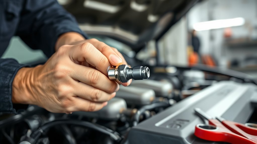
Do not replace a sensor based only on a trouble-code description. Follow a structured process and compare each result with Toyota’s procedure for the vehicle’s model year, engine, emissions calibration, bank, and position. DENSO’s O2 and A/F sensor troubleshooting guidance also emphasizes systematic diagnosis and confirmation of the completed repair.
[Amazon Products Picked for You]
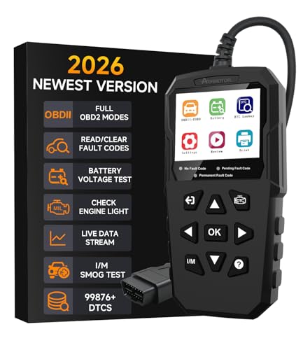
🚗 2026 Pro-Grade Diagnostics + 99,876 DTC Library — Pinpoint Faults with Precision:Check engine light on but not sure how serious? AERMOTOR V880 fully upgraded scan tool delivers professional-grade engine analysis with full access to all 10 OBD2 modes. Instantly access 99,876+ built-in DTC definitions directly on screen — no internet needed. Go further with Mode 6 (component-level monitoring) and Mode 8 (EVAP leak tests) to uncover hidden issues like misfires, O2 sensor failures, or EVAP leaks that basic code readers miss. Whether you're doing weekend maintenance or preparing for a smog check, get pro-level diagnostics right in your garage.

★【SAVES MONEY AND TIME】The KW850 car computer reader is a professional vehicle diagnostic tool for car owners to quickly read and erase DTC (engine fault codes) as well as a battery tester. A look-up library with over 8, 000 built-in generic code definitions allows you to accurately identify the cause of your CHECK ENGINE and perhaps fix it without going to see your dealer. It also assists you in easily passing annual emissions tests and SMOG CHECK. Perfect household tool and present for daily use! NEW REPLACEMENT AVAILABLE FOR ANY QUALITY ISSUE.

🚗 2026 Pro-Grade Diagnostics + 99,876 DTC Library — Pinpoint Faults with Precision:Check engine light on but not sure how serious? AERMOTOR V880 full upgraded scan tool delivers professional-grade engine analysis with full access to all 10 OBD2 modes. Instantly access 99,876+ built-in DTC definitions directly on screen — no internet needed. Go further with Mode 6 (component-level monitoring) and Mode 8 (EVAP leak tests) to uncover hidden issues like misfires, O2 sensor failures, or EVAP leaks that basic code readers miss. Whether you're doing weekend maintenance or preparing for a smog check, get pro-level diagnostics right in your garage.
1. Read Every Code and Save Freeze-Frame Data
Connect an OBD-II scan tool and record stored, pending, and permanent codes. Save freeze-frame information before clearing anything. Engine speed, coolant temperature, calculated load, fuel trims, vehicle speed, and fuel-system status can show the conditions under which the fault occurred.
One code may be the result of another. A misfire, airflow, coolant-temperature, or lean-mixture fault may explain unusual exhaust-sensor readings.
2. Confirm the Sensor, Bank, Position, and Circuit
Use the DTC definition and Toyota wiring diagram to confirm whether the monitored device is an A/F sensor or conventional O2 sensor. Identify the connector, heater terminals, signal or pump-current terminals, power source, ECM control, and applicable fuse before testing.
Do not assume that every code naming “oxygen sensor” refers to a narrowband unit. Generic scan tools may use broad terminology even when Toyota calls the upstream device an A/F sensor.
3. Inspect the Wiring, Connectors, and Exhaust
With the exhaust cool, inspect the sensor harness for melted insulation, chafing, stretched wires, damaged clips, previous splices, oil contamination, water entry, spread terminals, and corrosion. Confirm that the connector is fully seated and that the harness is not touching the exhaust.
Check for an exhaust leak upstream of the monitored sensor. A cracked manifold, loose flange, failed gasket, or damaged flex section can draw outside air into the exhaust and create a false lean indication.
4. Check Live Data at Operating Temperature
Start with the engine fully warm unless Toyota’s procedure specifies another condition. Review fuel-system status, upstream A/F data, downstream O2 data, commanded equivalence ratio, short-term fuel trim, long-term fuel trim, coolant temperature, mass airflow, engine speed, and control-module voltage.
Do not judge a wide-range sensor by expecting it to switch from about 0.1 to 0.9 volts like a conventional zirconia switching sensor. Select the Toyota A/F current, lambda, equivalence-ratio, or manufacturer-specific data item specified for that vehicle.
5. Compare Fuel Trims at Idle and Higher RPM
Fuel trims help separate a sensor problem from an engine problem. Positive trim means the ECM is adding fuel. Negative trim means it is removing fuel.
- Positive trim that improves noticeably above idle may point toward an intake or vacuum leak.
- Positive trim that remains high under load may involve low fuel pressure, restricted injector flow, unmetered air, an exhaust leak, or inaccurate airflow data.
- Negative trim may result from excess fuel, a leaking injector, high fuel pressure, incorrect purge flow, contaminated oil entering the intake, or biased sensor data.
- A large difference between banks on a V6 may point toward a bank-specific leak, injector problem, exhaust leak, or sensor circuit.
6. Test the Sensor’s Response
Graph the applicable upstream data while the engine moves through controlled operating changes specified by Toyota. A healthy wide-range sensor should respond in the expected direction when the ECM commands or observes a richer or leaner mixture. A conventional switching sensor should react appropriately after reaching operating temperature.
Do not create an uncontrolled vacuum leak, spray flammable chemicals into the intake, or add fuel manually. Where available, use Toyota active tests or the repair manual’s specified response procedure.
7. Test the Heater Circuit Correctly
A code such as P0135 refers generally to the Bank 1 Sensor 1 heater circuit. On a particular Camry, Sensor 1 may be a wide-range A/F sensor rather than a conventional O2 sensor. Test the specified fuse, power supply, ECM-controlled ground or power circuit, connector terminals, harness resistance, and sensor heater according to the Toyota wiring diagram.
Test at the conditions specified by Toyota. Some heater circuits use duty-cycle control, so a simple key-on voltage check may not tell the whole story.
Warning: Do not jump heater terminals, pierce sealed wiring, or apply a powered test light to ECM-controlled circuits. Use back-probing equipment and test methods approved for the circuit.
8. Rule Out Problems That Mimic a Bad Sensor
Before replacing the sensor, check for:
- Intake-manifold, brake-booster, PCV, or vacuum leaks
- Exhaust leaks before the sensor
- Dirty or inaccurate mass-airflow data
- Engine misfires
- Incorrect fuel pressure
- Restricted or leaking fuel injectors
- Coolant-temperature sensor faults
- EVAP purge flow at the wrong time
- Oil, coolant, silicone, or excess-fuel contamination
- Low charging voltage or poor grounds
- Incorrect replacement sensor calibration
Pro Tip: Graph the upstream sensor, downstream sensor, short-term fuel trim, long-term fuel trim, commanded lambda, and engine speed together. A graph makes slow response, dropouts, wiring interruptions, mixture changes, and downstream catalyst patterns easier to compare.
9. Verify the Diagnosis Before Ordering Parts
Replace the sensor only when the test results identify a slow, biased, contaminated, open, shorted, physically damaged, or out-of-specification sensor. Repair wiring, exhaust leaks, intake leaks, fuel faults, or grounds when those tests identify the actual cause.
| Finding | More Likely Direction | Next Check |
|---|---|---|
| Immediate heater or circuit code after startup | Fuse, power, ECM control, connector, wiring, heater, or wrong part | Follow the wiring diagram and heater test before replacing anything |
| Positive trims are high at idle but improve with RPM | Intake or vacuum leak | Smoke-test the intake and inspect PCV and vacuum hoses |
| Positive trims remain high under load | Fuel delivery, airflow measurement, exhaust leak, or sensor bias | Check fuel pressure, injector balance, MAF data, and exhaust sealing |
| Sensor data is fixed and fails a specified response test | Sensor, signal circuit, reference circuit, or ECM control fault | Verify terminal values, continuity, pin fit, and response with Toyota’s procedure |
| Downstream data resembles upstream data after other faults are corrected | Exhaust leak or reduced catalyst oxygen-storage ability | Evaluate leaks, fuel control, misfires, oil use, sensor operation, and converter condition |
| Sensor tip shows deposits or contamination | Oil burning, coolant entry, silicone contamination, or persistent rich running | Correct the contamination source before installing a new sensor |
Common Trouble Codes and What They Really Mean
The following are general examples. Toyota’s exact code definition, monitored sensor type, enable criteria, and diagnostic sequence can vary by model year, engine, and calibration. Always read the vehicle-specific Toyota definition before ordering a part.
| Code | General Meaning | What to Check |
|---|---|---|
| P0130 | Bank 1 Sensor 1 oxygen-sensor circuit malfunction in the generic code set | Confirm which sensor Toyota monitors under this code, then check connector, signal circuit, reference or ground, exhaust leaks, and sensor response |
| P0133 | Bank 1 Sensor 1 slow response in the generic code set | Aged or contaminated sensor, leaks, wiring, fuel-control problems, misfires, and the model-specific response test |
| P0135 | Bank 1 Sensor 1 heater-circuit malfunction in the generic code set | Fuse, supply voltage, ECM control, grounds, connector, wiring resistance, heater specification, and correct part number |
| P0171 | System too lean on Bank 1 | Vacuum leaks, PCV system, fuel pressure, injectors, MAF data, exhaust leaks, purge flow, misfires, and possible sensor bias |
| P0420 | Catalyst efficiency below threshold on Bank 1 | Exhaust leaks, misfires, fuel control, oil or coolant consumption, upstream data, downstream data, and converter condition |
| P1133 | Manufacturer-specific A/F sensor circuit response code used on some older Toyota applications, commonly involving Bank 1 Sensor 1 | Verify the Toyota definition, response test, wiring, exhaust sealing, mixture control, contamination, and correct sensor calibration |
| P1135 | Manufacturer-specific A/F sensor heater-circuit code used on some older Toyota applications | Confirm the bank and position, then test heater power, ECM control, connector, harness, and heater resistance to Toyota specifications |
| P2195 | Bank 1 Sensor 1 signal indicated or biased lean on applicable vehicles | Intake and exhaust leaks, fuel delivery, purge flow, wiring, sensor response, and whether the engine is actually lean |
| P2237/P2238 | A/F sensor pump-current circuit fault on applicable vehicles | Correct Toyota definition, connector pin fit, opens or shorts, harness routing, sensor compatibility, and ECM-side circuit tests |
A code identifies the monitor that detected a problem. It does not direct you to replace the named component without testing. The California Air Resources Board OBD program explains that OBD stores malfunction information so a technician can locate and repair the actual fault.
Best Practices for Maintaining and Replacing Camry Sensors
Oxygen and A/F sensors do not have one universal replacement interval for every Camry. Replace a sensor when testing confirms that it is slow, biased, contaminated, electrically open or shorted, physically damaged, incompatible, or outside Toyota’s specifications.
| Action | Best Practice | When |
|---|---|---|
| Verify the configuration | Match the VIN, engine, emissions label, bank, position, connector, harness length, and part number | Before ordering or installing a sensor |
| Inspect the harness | Look for heat damage, rubbing, corrosion, oil, water, poor pin fit, previous repairs, and incorrect routing | When a related code, impact, exhaust repair, or drivability symptom occurs |
| Correct contamination sources | Repair oil burning, coolant entry, silicone exposure, rich running, or repeated misfire before fitting a new sensor | Whenever deposits or contamination are found |
| Choose a quality direct-fit part | Use Toyota Genuine or a reputable OE-quality sensor cataloged for the exact application | Whenever replacement is confirmed |
| Avoid universal splicing | Do not change connectors or splice signal wiring unless the sensor manufacturer supplies an approved, application-specific procedure | During part selection and installation |
| Protect the sensor | Keep oil, coolant, silicone spray, grease, cleaners, penetrating fluid, and excess thread compound away from the sensing tip and connector | During engine and exhaust work |
| Verify the repair | Recheck live data, response, fuel trims, codes, leaks, harness routing, and readiness status | After installation or circuit repair |
Note: Do not treat solvent cleaning, wire brushing, torch heating, or soaking as a normal oxygen-sensor repair. These methods can damage the sensing element and do not correct the oil, coolant, silicone, fuel, or engine fault that caused contamination.
Functionally equivalent aftermarket replacement parts can work with OBD II when they are correctly designed and matched. CARB discusses compatible replacement parts in its OBD II systems fact sheet. Avoid unknown, counterfeit, universal, or incorrectly cataloged sensors.
How to Replace an Oxygen or Air-Fuel Ratio Sensor Safely
- Confirm the failed position. Verify the bank, sensor number, sensor type, and DTC procedure with a wiring diagram or Toyota repair manual.
- Save the diagnostic information. Record codes, freeze-frame data, fuel trims, and relevant sensor graphs before clearing OBD memory.
- Let the exhaust cool. Exhaust components can cause severe burns long after the engine is switched off.
- Raise the vehicle safely when required. Use a level surface, wheel chocks, correct lifting points, and rated jack stands. Never work under a vehicle supported only by a jack.
- Disconnect the electrical connector. Release its lock without pulling on the wires. Note the original routing and clip positions.
- Remove the sensor. Use the correct oxygen-sensor socket or wrench. Avoid damaging nearby heat shields, exhaust threads, wiring, or connectors.
- Inspect the old sensor and threads. Look for impact damage, deposits, coolant residue, oil contamination, damaged threads, or signs that the harness contacted the exhaust.
- Compare the parts. Check the connector, wire length, thread size, sealing surface, sensor type, and part number before installation.
- Follow the sensor manufacturer’s instructions. Many new sensors have thread compound already applied. Do not add anti-seize unless the instructions call for it, and never place compound on the sensing tip.
- Torque it correctly. Use the specification in Toyota’s repair manual for the exact sensor and exhaust component.
- Route the harness properly. Keep it away from the exhaust, moving parts, and sharp edges. Reinstall every clip and heat shield.
- Verify the repair. Start the engine, check for an exhaust leak, review scan data, confirm correct response, and make sure the harness remains secure.
Note: On a Camry Hybrid, stay clear of orange high-voltage cables and components. Exhaust-sensor replacement normally does not require opening the high-voltage system, but follow Toyota’s hybrid safety procedures whenever nearby components, undercovers, or heat shields must be removed.
[Amazon Products Picked for You]

Efficient O2 Sensor Removal: This O2 sensor wrench is designed for quick removal and installation of 7/8" (22mm) oxygen sensors. Built for professional mechanics and DIY users, it delivers reliable performance even in tight engine spaces

O2 Sensor Socket Set: The package includes 1/2" Dr. x 1-3/16" (29mm) vacuum switch socket, 1/2" Dr. x 7/8" (22mm) vacuum switch socket, 1/2" Dr. x 1-1/16" (27mm) thermal sensor switch socket, 3/8" Dr. x 1" & 1-1/16" oil pressure sending unit socket, 3/8" Dr. x 7/8" long oxygen sensor socket, 3/8" Dr. x 7/8" offset oxygen sensor wrench, and 1/2" Dr. x 7/8" heated oxygen sensor socket

180° Rotatable Head: This automotive oxygen sensor socket wrench features a 180° rotatable socket head for enhanced flexibility. The swivel joint allows you to freely adjust the socket angle without additional tools, enabling access to oxygen sensors mounted near exhaust manifolds, oil pans, or other confined fasteners.
When Professional Repair Is the Safer Choice
Professional diagnosis or repair is advisable when:
- The sensor is seized or the exhaust bung begins to deform
- Exhaust threads are damaged or require repair
- A circuit code returns immediately with a known-correct sensor
- The wiring disappears into a difficult harness section
- Toyota active tests, an oscilloscope, or current measurements are required
- Hybrid high-voltage components or orange cables interfere with access
- The vehicle has a flashing check-engine light, severe misfire, unstable running, or an overheated converter
What to Check if the Code Returns After Replacement
If the same code returns immediately, check the connector, heater power, ECM control, ground, fuse, wiring continuity, terminal tension, part number, sensor position, and calibration. An immediate circuit code commonly points toward an electrical, installation, or compatibility problem rather than ordinary sensor aging.
If a lean or rich code returns, inspect the intake system, exhaust, MAF data, fuel pressure, injectors, EVAP purge system, coolant-temperature reading, PCV system, and misfire counters. Replacing an A/F sensor will not correct an air leak, fuel-delivery fault, inaccurate airflow reading, or purge problem.
If P0420 returns, do not assume the downstream sensor caused it. Evaluate exhaust leaks, misfires, oil or coolant consumption, fuel control, upstream sensor operation, downstream sensor behavior, and catalytic-converter oxygen-storage performance.
Clear codes only after saving the original diagnostic information and completing the repair. Clearing OBD memory resets readiness information. The vehicle may need several normal trips under suitable operating conditions before all supported emissions monitors run again. There is no single universal Camry drive cycle that fits every year and calibration.
Sources
- Toyota Manuals and Warranties — VIN- and model-specific owner information
- Toyota Technical Information System — repair manuals, wiring diagrams, diagnostics, active tests, and service procedures
- DENSO O2 and A/F Sensor Troubleshooting — systematic diagnosis, sensor identification, location, and narrowband signal guidance
- California Air Resources Board OBD II Systems Fact Sheet — check-engine-light, stored-fault, repair, readiness, and replacement-part guidance
- Bosch Lambda Sensor History — lambda control, stoichiometry, catalytic-converter operation, and switching-versus-wideband characteristics
- SAE Technical Paper 920234 — wide-range air-fuel ratio sensor design, response, and operating principle
Frequently Asked Questions
Is the Air-Fuel Ratio Sensor the Same as the Oxygen Sensor?
Not exactly. An air-fuel ratio sensor is a wide-range oxygen-sensing device, while the term oxygen sensor often refers to a conventional narrowband switching unit. They use different control circuits, calibration, and signal strategies, so they are not interchangeable.
What Sensor Controls the Air-Fuel Ratio?
No single sensor controls it. The ECM controls injector operation using the upstream A/F or oxygen sensor together with airflow, temperature, throttle, engine speed, load, and other data. The upstream exhaust sensor supplies feedback that helps the ECM correct the mixture during closed-loop operation.
How Many Oxygen Sensors Does a Toyota Camry Have?
The number varies by model year, engine, exhaust layout, hybrid status, market, and emissions certification. Many four-cylinder Camrys use one upstream A/F sensor and one downstream oxygen sensor. V6 and other configurations may use more. Check the VIN and exhaust diagram before ordering.
What Happens When an Air-Fuel Ratio Sensor Goes Bad?
Possible symptoms include a check-engine light, abnormal fuel trims, reduced fuel economy, hesitation, rough running, and an emissions-test failure. Intake leaks, exhaust leaks, misfires, fuel problems, airflow errors, or damaged wiring can produce the same symptoms, so test before replacing the sensor.
Can You Drive With a Bad Air-Fuel Ratio Sensor?
Limited driving may be possible with a steady check-engine light and otherwise normal operation, but fuel economy, emissions, and drivability can worsen. Have the fault diagnosed soon. Stop driving when the light flashes, the engine misfires heavily, power falls sharply, or the converter becomes unusually hot.
Should You Replace Both Sensors at the Same Time?
Usually not. Replace the sensor or circuit component that testing identifies as faulty. Upstream and downstream sensors perform different jobs, and one failed sensor does not prove that the other has reached the end of its service life.
Does a Toyota Air-Fuel Ratio Sensor Always Read 3.3 Volts?
No. Some Toyota applications and scan tools may display a processed value near 3.3 volts around stoichiometric operation, but that number is not a universal raw-output specification. Other tools may show pump current, lambda, or equivalence ratio. Use the specified Toyota data item and limits for the vehicle.
Can You Clean an Oxygen or Air-Fuel Ratio Sensor?
Cleaning is not a dependable routine repair. Solvents, wire brushes, torch heating, and chemical soaking can damage the sensing element or create only a temporary change. Diagnose the sensor and correct the oil, coolant, silicone, fuel, or engine fault that caused contamination before installing a verified replacement.
Conclusion
Your Toyota Camry’s air-fuel ratio sensor and conventional oxygen sensor both respond to exhaust oxygen, but they differ in operating range, control circuit, scan data, location, and purpose. The upstream sensor usually supports fuel control, while the downstream sensor commonly helps monitor the catalytic converter.
Do not rely on one voltage, one trouble code, a product photo, or a generic sensor count. Save the diagnostic data, identify the exact bank and position, inspect the wiring and exhaust, compare fuel trims, test the correct data item, and rule out engine and fuel-system faults. Confirming the VIN-specific part and procedure prevents unnecessary replacement and gives you a better chance of fixing the actual problem.
