The number of oxygen-sensing units in a 2010 Toyota RAV4 depends on its engine. The 2.5-liter four-cylinder has two, while the 3.5-liter V6 has four. Toyota usually calls the upstream units air-fuel-ratio sensors and the downstream units oxygen sensors, so parts listings may use both terms.
Quick Answer
A 2010 Toyota RAV4 with the 2.5L four-cylinder engine has two oxygen-sensing units: one upstream A/F ratio sensor and one downstream O2 sensor. The 3.5L V6 has four: two upstream A/F ratio sensors and two downstream O2 sensors, with one pair serving each cylinder bank.
Key Takeaways
- The 2.5L 2AR-FE engine has two sensors: Bank 1 Sensor 1 and Bank 1 Sensor 2.
- The 3.5L 2GR-FE V6 has four sensors: Sensor 1 and Sensor 2 for both Bank 1 and Bank 2.
- Toyota normally calls Sensor 1 an air-fuel-ratio sensor and Sensor 2 an oxygen sensor.
- A trouble code identifies a circuit or operating condition. It does not prove that the named sensor is defective.
- Confirm the engine, sensor position, emissions specification, and part number by VIN before ordering a replacement.
At a Glance
| Time Required | About 45 minutes to 2 hours for one sensor, depending on its location, access, and corrosion |
| Difficulty | Moderate; V6 and seized-sensor jobs can be more difficult |
| Tools Needed | OBD-II scan tool, oxygen-sensor socket or 22mm wrench, ratchet, penetrating oil, torque wrench, wheel chocks, ramps or jack stands as needed |
| Cost | Varies by engine, bank, sensor position, part brand, labor rate, and whether wiring or exhaust repairs are also needed |
How Many Oxygen Sensors Does the 2010 Toyota RAV4 Have?
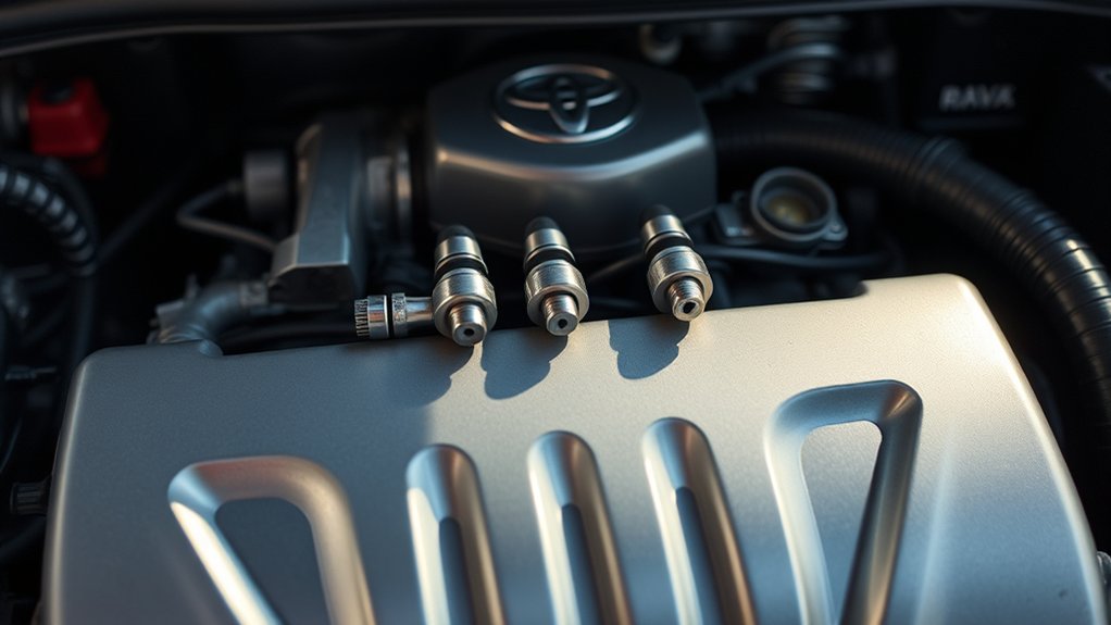
The standard U.S.-market sensor count is based on the engine:
| Engine | Total | Upstream | Downstream | Scan-tool names |
|---|---|---|---|---|
| 2.5L 2AR-FE inline-four | 2 | 1 A/F ratio sensor | 1 O2 sensor | B1S1 and B1S2 |
| 3.5L 2GR-FE V6 | 4 | 2 A/F ratio sensors | 2 O2 sensors | B1S1, B1S2, B2S1, and B2S2 |
The four-cylinder has one cylinder bank and one exhaust-monitoring pair. The V6 has two cylinder banks, so it uses one upstream and one downstream unit for each bank.
You can confirm the available engine configurations in the 2010 Toyota RAV4 Owner’s Manual. Sensor part numbers can still vary by production specification, emissions certification, and superseded part number, so confirm fitment with the full VIN.
Note: Front-wheel drive versus four-wheel drive does not normally change the basic two-sensor or four-sensor count. Engine type and exhaust configuration are the key factors.
How to Identify Your RAV4’s Engine
Before buying a sensor, determine whether your RAV4 has the 2.5L four-cylinder or 3.5L V6. You can check:
- The engine information in your registration or vehicle records
- The emissions-information label under the hood
- The VIN through a Toyota dealer or Toyota’s parts lookup
- The engine code shown in service documentation
The four-cylinder engine code is 2AR-FE. The V6 engine code is 2GR-FE. Do not rely only on the trim badge, drive type, or a generic online listing.
Understanding Upstream and Downstream Sensors
The upstream and downstream sensors work in the same exhaust system, but they perform different jobs.
Upstream Air-Fuel-Ratio Sensor
Sensor 1 sits before the catalytic converter. Toyota generally calls it an air-fuel-ratio sensor, or A/F sensor. It gives the engine control module detailed feedback about the exhaust mixture so the computer can adjust fuel delivery.
Toyota’s official parts information describes an A/F sensor as a component that monitors the air-and-fuel mixture and sends that information to the engine control system. You can see this terminology on Toyota’s Air Fuel Ratio Sensor information page.
Downstream Oxygen Sensor
Sensor 2 sits after the catalytic converter. It helps the vehicle monitor converter performance by comparing post-catalyst exhaust oxygen activity with the upstream reading.
Toyota lists these units separately as oxygen sensors in its official oxygen-sensor parts information.
On Toyota scan data, Sensor 1 is normally the upstream A/F ratio sensor. Sensor 2 is normally the downstream oxygen sensor.
What Bank and Sensor Numbers Mean
- Bank 1: The side of the engine containing cylinder number 1.
- Bank 2: The opposite cylinder bank on the V6. The inline-four does not have Bank 2.
- Sensor 1: The sensor located before that bank’s catalytic converter.
- Sensor 2: The sensor located after that bank’s catalytic converter.
The NTK oxygen-sensor technical guide illustrates the standard B1S1, B1S2, B2S1, and B2S2 naming system. Do not identify a V6 bank only by calling it the driver or passenger side. Transverse-engine orientation can make informal left-and-right descriptions confusing.
Oxygen-Sensor Layout by Engine Type
2.5L Four-Cylinder Sensor Layout
The 2.5L 2AR-FE engine has one exhaust bank:
- Bank 1 Sensor 1: The upstream air-fuel-ratio sensor, positioned before the catalytic converter.
- Bank 1 Sensor 2: The downstream heated oxygen sensor, positioned after the catalytic converter.
Because the engine has one cylinder bank, it does not use Bank 2 sensor designations.
3.5L V6 Sensor Layout
The 3.5L 2GR-FE engine has two cylinder banks:
- Bank 1 Sensor 1: Upstream A/F ratio sensor for Bank 1
- Bank 1 Sensor 2: Downstream O2 sensor for Bank 1
- Bank 2 Sensor 1: Upstream A/F ratio sensor for Bank 2
- Bank 2 Sensor 2: Downstream O2 sensor for Bank 2
Access differs among the four positions. One V6 sensor may be visible from above, while another may require safe under-vehicle access or removal of nearby shields and clips.
Pro Tip: Record the exact code, engine, bank, sensor number, connector shape, wire length, and original part number before ordering. A part described only as “fits 2010 RAV4” may not fit every engine or sensor position.
Common RAV4 Oxygen-Sensor Issues
A check-engine light can be related to the sensor element, heater circuit, wiring, connector, exhaust system, air-fuel mixture, catalytic converter, or engine-control logic. Do not replace a sensor based only on the wording of one code.
Possible problems include:
- Open, shorted, melted, or high-resistance wiring
- Loose, corroded, contaminated, or water-damaged connectors
- An exhaust leak near a sensor or catalytic converter
- A damaged sensor heater circuit or fuse
- Oil, coolant, silicone, soot, or fuel contamination
- A vacuum leak, injector issue, fuel-pressure problem, or incorrect mixture
- A failing catalytic converter
- ECM calibration or processor-related faults
Understanding Common Trouble Codes
| Code | General meaning | What to check |
|---|---|---|
| P0138 | O2 sensor circuit high voltage, Bank 1 Sensor 2 | Freeze-frame data, B1S2 circuit, wiring, mixture conditions, and upstream A/F sensor response |
| P0158 | O2 sensor circuit high voltage, Bank 2 Sensor 2 | The corresponding Bank 2 circuit and sensor data on a V6 |
| P2195 | A/F sensor signal stuck lean, Bank 1 Sensor 1 | Air leaks, fuel delivery, wiring, exhaust leaks, and A/F sensor operation |
| P2197 | A/F sensor signal stuck lean, Bank 2 Sensor 1 | The corresponding Bank 2 mixture, circuit, and A/F sensor on the V6 |
| P0606 | ECM/PCM processor fault | Battery voltage, grounds, related codes, sensor operation, wiring, and Toyota’s diagnostic procedure |
Toyota issued Technical Service Bulletin T-SB-0001-10 for certain vehicles, including 2006–2010 RAV4 models, that may store P0138, P0158, P2195, P2197, or P0606 in related conditions. The bulletin uses freeze-frame values and circuit checks to decide whether the upstream A/F sensor, downstream circuit, wiring, or another component needs attention.
Warning: A diagnostic trouble code does not automatically condemn the sensor named in the code. Replacing parts without checking scan data, wiring, exhaust leaks, and mixture conditions can leave the original fault unresolved.
Symptoms That May Occur
Depending on the fault, you may notice:
- An illuminated check-engine light
- Reduced fuel economy
- Rough idle or hesitation
- Poor acceleration
- A failed emissions inspection
- A strong exhaust or fuel smell
- No noticeable drivability symptoms at all
These symptoms are not unique to an oxygen sensor. Ignition, fuel, intake, exhaust, and catalytic-converter problems can produce similar results.
When Should You Replace an Oxygen Sensor?
Replace a sensor when testing shows that its element, heater, wiring lead, or connector has failed and the underlying cause has been corrected. Toyota does not provide a blanket rule requiring every sensor to be replaced at a specific odometer reading.
A sound diagnosis normally includes:
- Reading all stored, pending, and permanent trouble codes
- Saving freeze-frame data before clearing anything
- Confirming the engine, bank, and sensor position
- Inspecting the harness, connector, clips, and routing
- Checking for exhaust leaks ahead of or near the sensor
- Reviewing live A/F and O2 sensor data
- Testing the heater and circuit according to service information
- Checking fuel trims and other evidence of a rich or lean condition
DENSO’s O2 and A/F sensor troubleshooting guidance recommends investigating the cause of an abnormal rich or lean reading before replacing the sensor.
Note: Replacing one failed sensor does not normally require replacing every other sensor. Replace additional units only when diagnosis, physical damage, or a planned repair justifies it.
How the Sensors Affect Performance and Emissions
Effect on Fuel Control and Fuel Economy
The upstream A/F sensor helps the engine control module make fuel-delivery corrections after the system enters closed-loop operation. An inaccurate signal can contribute to an overly rich or lean mixture, but mixture problems elsewhere can also make a properly working sensor report abnormal values.
A rich mixture may increase fuel use, carbon buildup, and exhaust emissions. A lean condition may cause hesitation, rough operation, or excessive combustion temperature. Accurate diagnosis must separate the sensor’s report from the condition it is reporting.
Effect on Catalytic-Converter Monitoring
The downstream sensor helps the OBD system evaluate catalytic-converter performance. If its signal activity is too similar to the upstream signal, the control module may determine that the converter is not storing and processing oxygen as expected.
| Sensor | Primary role | Possible effect of a fault |
|---|---|---|
| Upstream A/F ratio sensor | Provides mixture feedback for fuel control | Incorrect fuel correction, rough operation, reduced economy, or increased emissions |
| Downstream O2 sensor | Supports catalytic-converter monitoring | Incorrect catalyst-monitor results, warning light, or emissions-test failure |
| Sensor heater | Brings the sensing element to operating temperature | Slow closed-loop entry, heater codes, or incomplete monitor operation |
Steps for Replacing an Oxygen Sensor
Warning: Work on a level surface. Set the parking brake and chock the wheels. Use properly rated ramps or jack stands at approved lift points. Never work beneath a vehicle supported only by a jack. Allow the exhaust to cool enough to prevent burns, and keep penetrating oil away from ignition sources.
- Diagnose the fault first. Read the codes and freeze-frame data. Confirm that the sensor or its circuit has failed before buying a replacement.
- Identify the exact position. Record the engine, bank, sensor number, original connector, and part number. Verify the replacement by VIN.
- Prepare the vehicle. Park on a level surface, switch off the ignition, remove the key, set the parking brake, and chock the wheels. Raise and support the vehicle safely only if the sensor requires underbody access.
- Disconnect the electrical connector. Release the lock without pulling on the wires. Remove harness clips as needed and note the original routing.
- Apply penetrating oil if necessary. Apply a small amount around the sensor threads and allow it time to work. Keep the product off the connector and sensing tip.
- Remove the old sensor. Use an oxygen-sensor socket or suitable 22mm wrench. Avoid rounding the hex or twisting the harness around nearby parts.
- Compare the old and new parts. Confirm the connector, wire length, thread size, protective shield, and part number before installation.
- Install the direct-fit sensor. Start it by hand to prevent cross-threading. Use anti-seize only when the replacement instructions call for it and it is not already pre-applied. Never put compound on the sensing tip.
- Tighten it correctly. Use the torque specification supplied by Toyota service information or the sensor manufacturer. Do not guess or overtighten it.
- Reconnect and route the harness. Reinstall every clip and keep the wire away from hot exhaust parts, sharp edges, and moving components.
- Complete the repair check. Reconnect the battery if it was disconnected, clear codes with a scan tool when appropriate, start the engine, check for exhaust leaks, and verify live data.
- Confirm monitor operation. Road-test the vehicle under safe conditions. Remember that clearing codes or disconnecting the battery resets OBD readiness monitors, which may need several normal trips before an emissions inspection.
Pro Tip: Take a photo of the original harness routing and connector position before removal. Correct routing helps prevent melted wires, tension on the connector, and repeat faults.
Tools and Supplies You May Need
- OBD-II scan tool with live-data capability
- Oxygen-sensor socket or 22mm box-end wrench
- Ratchet and suitable extensions
- Torque wrench covering the required range
- Penetrating oil
- Wheel chocks
- Properly rated ramps or jack stands when underbody access is necessary
- Safety glasses and work gloves
- Small pick or connector tool for stubborn locking tabs
- VIN-matched direct-fit replacement sensor
- Anti-seize compound only if the sensor manufacturer requires it and none is pre-applied
A specialty oxygen-sensor socket has a slot that clears the wiring lead. It is usually safer and easier than forcing an open-end wrench into a restricted area.
Avoid using a lighter or other open flame on the wiring, connector, penetrating oil, or exhaust components. Do not cut the factory connector to install a universal sensor unless the sensor manufacturer supplies an approved application-specific procedure.
How to Identify the Correct Replacement Sensor
Use all of the following details when selecting a replacement:
- Model year: 2010
- Engine: 2.5L 2AR-FE or 3.5L 2GR-FE
- Position: Upstream Sensor 1 or downstream Sensor 2
- Bank: Bank 1 or Bank 2 on the V6
- Emissions specification: Confirm through the underhood label or VIN lookup
- Connector and wire length: They must match the intended position
- Original or superseding part number: Verify through Toyota or a reliable parts catalog
A direct-fit sensor includes the correct connector and application-specific wire length. It reduces the risk of incorrect splices, reversed wires, poor sealing, and routing problems.
DIY Replacement Tips and Common Challenges
Removing a Seized Sensor
Heat cycles and corrosion can make a sensor difficult to remove. Use penetrating oil and the correct socket, and apply steady force. Avoid hammering nearby exhaust components or using an uncontrolled flame.
If the sensor hex begins to round, the exhaust bung moves, or the pipe starts twisting, stop. A repair shop may need to use controlled heat, specialty tools, or exhaust-component removal to prevent more expensive damage.
Handling Tight Connectors and Wiring
Connector locks can become brittle with age. Depress the locking tab instead of pulling on the wires. If access is limited, release nearby harness clips first rather than stretching the lead.
Inspect the entire harness for:
- Melted insulation
- Contact with the exhaust
- Broken retaining clips
- Corroded terminals
- Water or oil in the connector
- Previous non-factory splices
Repair vehicle-side wiring with the correct automotive wiring procedure and materials. Do not assume that installing another sensor will correct damaged wiring.
What to Do if the Code Returns
If the same code returns after replacement, recheck:
- The sensor’s bank and position
- The replacement part number and connector
- Harness routing and terminal contact
- Exhaust leaks
- Fuel trims and mixture-related codes
- Heater power, ground, resistance, and fuses
- Applicable Toyota service bulletins or ECM calibration information
- Catalytic-converter operation when the diagnosis points to it
Do not continue replacing sensors until the code disappears. Repeated sensor codes often indicate an unresolved circuit, mixture, exhaust, or control-system problem.
Related Guides
Frequently Asked Questions
Can I drive my RAV4 with a faulty oxygen sensor?
A short trip may be possible when the RAV4 runs normally and the check-engine light is steady, but you should arrange diagnosis promptly. Stop driving and seek help if the engine misfires, loses substantial power, overheats, stalls, produces strong fuel odors, or shows another serious warning. Toyota advises contacting a dealer if the malfunction indicator lamp remains on after basic fuel-cap and fuel-level checks.
How much does it cost to replace a 2010 RAV4 oxygen sensor?
The total depends on the engine, bank, sensor position, part brand, local labor rate, corrosion, and whether wiring or exhaust repairs are required. An upstream A/F sensor may also cost differently from a downstream O2 sensor. Request a quote based on the VIN and exact sensor position rather than relying on a generic price range.
What symptoms can indicate an oxygen-sensor problem?
Possible signs include a check-engine light, poor fuel economy, rough idle, hesitation, increased emissions, or an emissions-test failure. However, exhaust leaks, wiring faults, ignition problems, fuel-delivery issues, vacuum leaks, and catalytic-converter faults can cause similar symptoms.
Will a bad oxygen sensor turn on the check-engine light?
It can. The engine control module monitors sensor signals, heater operation, response time, and related circuits. A fault may store a code and illuminate the malfunction indicator lamp. The code still needs diagnosis because wiring, mixture, exhaust, or control-module problems can produce sensor-related codes.
Can I clean an oxygen sensor instead of replacing it?
Cleaning is not a dependable repair for an internally failed, slow, poisoned, or heater-damaged sensor. Solvents can damage the sensing element or leave contamination. Diagnose and correct the source of oil, coolant, silicone, soot, or mixture contamination, then replace the sensor if testing confirms that it has failed.
Do I need to replace all the sensors at the same time?
No. Replace the sensor that has been correctly diagnosed as faulty. The other sensors can remain in service when their signals, heaters, wiring, and connectors test normally.
Is Bank 1 Sensor 1 the same part as Bank 1 Sensor 2?
Usually not. Bank 1 Sensor 1 is the upstream A/F ratio sensor, while Bank 1 Sensor 2 is the downstream oxygen sensor. They can use different sensing technology, connectors, wire lengths, and part numbers.
Conclusion
A 2010 Toyota RAV4 has two oxygen-sensing units with the 2.5L four-cylinder or four with the 3.5L V6. Sensor 1 is normally Toyota’s upstream air-fuel-ratio sensor, while Sensor 2 is the downstream oxygen sensor.
Confirm the engine, bank, position, emissions specification, and VIN before ordering. When a warning light appears, diagnose the full circuit and operating condition instead of replacing the sensor named in the code. If you perform the repair yourself, use a direct-fit part, support the vehicle correctly, protect the wiring, and follow the applicable torque and installation instructions.
Sources
- 2010 Toyota RAV4 Owner’s Manual — engine identification, warning-light guidance, OBD readiness, and vehicle specifications
- Toyota Technical Service Bulletin T-SB-0001-10 — diagnostic guidance for P0138, P0158, P2195, P2197, and P0606
- NTK Oxygen Sensors Technical Guide — bank and sensor naming, direct-fit guidance, sensor types, and installation practices
- DENSO O2 and A/F Sensor Troubleshooting — rich, lean, circuit, and sensor-diagnosis guidance
- Toyota Air Fuel Ratio Sensor Information — Toyota’s upstream A/F sensor terminology and function
- Toyota Oxygen Sensor Information — Toyota’s oxygen-sensor terminology and exhaust-monitoring function