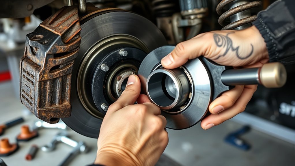
Removing the right-hand front wheel bearing on a 2017 model begins with confirming the fault through noise, play, or an ABS warning. Once the vehicle is safely supported, the brake and axle components are stripped back to reach the hub assembly. The bearing is then separated from the knuckle with the proper puller or slide hammer, but the final fit and torque details are where the job can turn critical.
Confirm a Bad Right Front Wheel Bearing
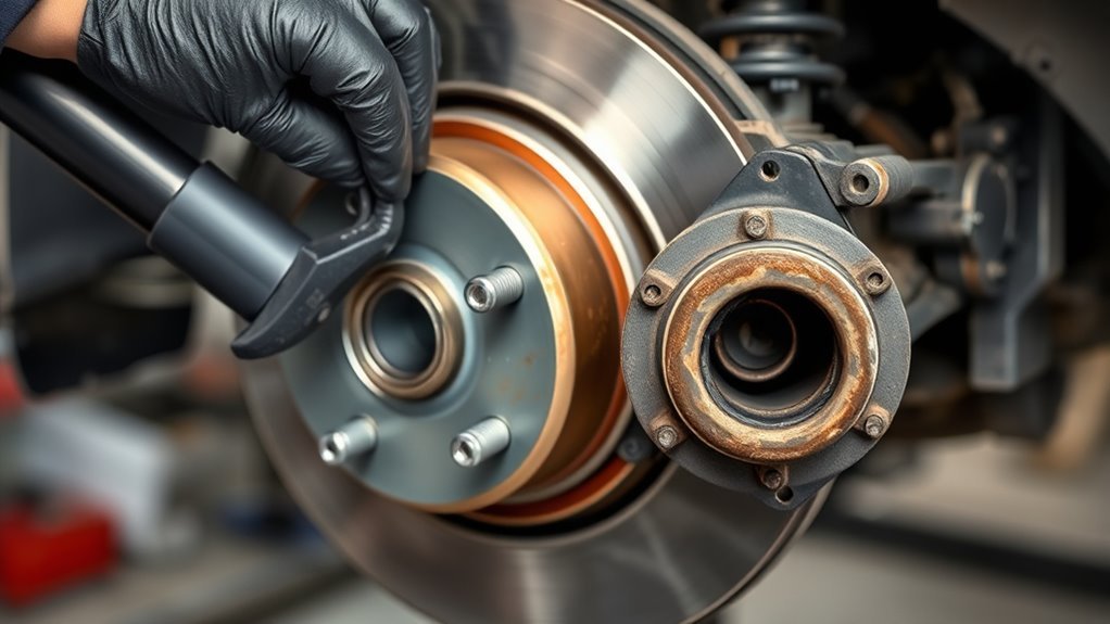
Before removing the front wheel bearing, confirm the right front assembly is actually faulty. A rumbling noise that rises with speed often points to a failing bearing, but noise alone is not enough.
The ABS and traction control lamps may also illuminate when the wheel hub assembly is compromised. A scan tool should be used to read the control module; codes such as C1233 and C1155 commonly support the diagnosis.
Because the ABS sensor is integrated into the bearing assembly, its signal can help separate a sensor fault from a mechanical failure.
Visual inspection should then be performed for play, heat discoloration, seal damage, or rough rotation. These checks help confirm a bad right front wheel bearing before any parts are removed.
Clear diagnosis prevents wasted labor, unnecessary replacement, and mechanical dependence on guesswork. Only after the fault is verified should the repair proceed.
Gather Tools and Raise the Car Safely
Required tools should be assembled first, including a breaker bar, 21 mm and 15 mm sockets, a ratchet, and a slide hammer kit for stubborn hub removal.
The vehicle should then be raised securely on jack stands with the rear tires blocked, and a tire placed under the vehicle as a backup safety measure.
If accessible, the center cap can be removed before lifting, or the tire can be taken off to expose the axle nut and bearing area.
Gather Required Tools
Gather the necessary tools first: a breaker bar, socket set with 15 mm and 21 mm sockets, torque wrench, slide hammer kit, penetrating fluid, abrasive sponge, and sandpaper.
These tools support efficient bearing removal and reduce wasted motion.
Before lifting, loosen the lug nuts while the tire remains on the ground.
Then use a hydraulic jack to raise the vehicle and place wheel chocks behind the rear tires so the chassis stays controlled.
Secure the front with jack stands under the frame to prevent collapse.
Keep the abrasive sponge and sandpaper ready for cleaning contact surfaces before installation.
With the proper tools organized, the work proceeds with discipline, safety, and independence.
Secure Vehicle On Stands
Park the vehicle on a flat, stable surface and engage the parking brake to prevent any movement during service.
The operator should then gather the jack, jack stands, breaker bar, and correct sockets, including 21 mm for caliper bolts and 15 mm for the hub assembly.
Before lifting, block the rear tires with wheel chocks or sturdy materials so the vehicle remains fixed.
Raise the front with the jack, then position the jack stands under the designated lifting points.
Lower the weight onto the stands and make sure the vehicle is stable before reaching under it.
This step is essential to secure the vehicle on stands and create a controlled, safe workspace.
Keep all tools within reach to support efficient, independent work.
Remove the Brake Caliper and Axle Nut
The brake caliper and rotor should be removed as a single assembly by loosening the two caliper bracket bolts with a 21 mm socket.
The axle nut is then loosened with a breaker bar, using a screwdriver to hold resistance; if it resists, penetrating fluid can help.
Once the brake components are clear, the rotor is out of the way and the hub assembly is accessible for further disassembly.
Remove Caliper Assembly
With the vehicle secured on jack stands and the rear tires blocked, the right front wheel can be removed to expose the brake caliper assembly.
To remove the caliper assembly, the two 21 mm bracket bolts are loosened and backed out evenly. The caliper and rotor are then withdrawn as one unit, with the assembly supported so the brake line is not strained or twisted.
A breaker bar is used to remove the axle nut, and a screwdriver may be placed to hold the rotor from turning while torque is overcome.
Once the nut is off, the ABS sensor wire is disconnected from the old bearing assembly.
Clean mating surfaces now, preparing for a clean, disciplined reassembly later.
Loosen Axle Nut
After the vehicle is securely supported on jack stands and the rear wheels are blocked, the brake caliper assembly is removed by backing out the two 21 mm bracket bolts and lifting the caliper and rotor off as a unit, taking care to support the assembly so the brake line is not strained.
With access opened, the axle nut can be addressed. A breaker bar and correct socket are placed on the nut, and steady force is applied to loosen axle nut from its 190 ft-lb preload. A screwdriver is used as resistance to prevent shaft rotation.
Once the nut breaks free, it is spun off completely and set aside. The exposed area is cleaned of debris before bearing service continues, preserving a clear path for reassembly and mechanical freedom.
Clear Brake Rotor
Loosen the two 21 mm caliper bracket bolts and detach the brake caliper from the rotor, then secure the caliper so the brake line is not strained.
With the caliper free, the technician can clear brake rotor access and remove the assembly without fighting hidden resistance. If the rotor is still trapped, confirm the caliper is fully out of the way before pulling it off.
A breaker bar should be used to loosen the axle nut; a screwdriver can be used to hold resistance if needed. Remove the axle nut completely to open wheel-end clearance, then slide off the rotor.
Any lug nuts removed earlier should be kept organized. Inspect the hub for rust, scale, or debris, because a clean surface supports smooth bearing installation and precise reassembly.
Extract the Wheel Bearing Hub Assembly
Begin by removing the brake caliper and rotor as a single unit by loosening the two 21 mm caliper bracket bolts.
With the brake hardware out of the way, disconnect the ABS sensor from the old bearing and remove the 8 mm screw securing the ABS wire. This frees the harness before the hub moves.
Next, loosen the axle nut with a breaker bar while holding resistance with a screwdriver, then remove the three 15 mm bolts that retain the wheel bearing hub assembly to the knuckle.
If corrosion has locked the hub in place, apply penetrating fluid at the interface between the hub and knuckle. Let it work, then use a slide hammer kit to pull the assembly free with controlled force. Keep the extraction straight to avoid damaging the mating surfaces.
Once removed, the path is clear for the next step and the old assembly can be set aside without interference from the liberated brake and sensor components.
Install the New Right Front Wheel Bearing
With the vehicle securely supported on jack stands and the right front wheel removed, the new Motch wheel bearing hub assembly can be positioned in the knuckle and the ABS harness routed and connected correctly to prevent future faults.
Install the new right front wheel bearing by aligning the hub squarely with the knuckle bores, then start all bearing bolts by hand to avoid cross-threading. The ABS sensor lead should be clipped back into its retainer and secured with the 8 mm screw so the wire remains free of pinch points.
Align the hub squarely, hand-start the bolts, and secure the ABS lead to prevent pinch points.
Tighten the bearing fasteners evenly in a crisscross pattern to seat the assembly without distortion. Inspect the axle splines for clean engagement and confirm the hub sits flush against the knuckle face.
Proper fit restores precise wheel control and preserves the system’s ability to report speed data without interference.
Reassemble, Torque, and Test the Repair
Once the new wheel bearing hub assembly is seated and the ABS lead is secured, the remaining components can be reinstalled and torqued to specification.
The axle nut should be installed and torqued to 190 ft-lb, with the hub and axle kept evenly aligned to protect structural integrity.
Caliper bolts may then be positioned, hand-tightened, and torqued to 100 ft-lb each to preserve braking performance.
The wheel bearing bolts should be secured with Loctite and tightened fully to resist vibration and loosening under load.
Lug nuts should be snugged while the vehicle is raised, then torqued to 100 ft-lb once the vehicle is back on the ground. This sequence keeps clamping force correct and prevents distortion.
After assembly, the vehicle can be lowered, the fasteners checked, and a short test drive completed. Proper ABS and traction control warning lamp behavior indicates the repair has been completed successfully.
Frequently Asked Questions
How to Get a Wheel Bearing off Without a Puller?
It can be freed without a puller by soaking the hub with penetrating fluid, then removing the axle nut completely.
For Bearing Extraction, a slide hammer with hub attachment provides the best controlled force. Sharp outward pulls help break rust bonds. If it resists, tap around the knuckle, then apply gentle heat to expand the metal.
The process demands patience, not surrender, and each step should avoid damaging the hub or axle.
What Is the Easiest Way to Remove a Wheel Bearing?
The easiest way to remove a wheel bearing is to raise the vehicle securely, remove the tire, and free the axle nut with a breaker bar.
Then disconnect the ABS sensor, apply penetrating fluid at the hub-knuckle joint, and use Bearing Tools or a slide hammer to pull the hub assembly.
A screwdriver can stop rotation during loosening.
After removal, anti-seize should be applied to ease future maintenance and preserve independence.
How to Change Right Wheel Bearing?
The right wheel bearing changes by lifting the vehicle, removing the wheel, caliper, rotor, axle nut, and hub bolts, then extracting the hub with a slide hammer if needed.
Coincidentally, clean removal and proper torque prevent repeat failure.
Bearing Maintenance demands Loctite, ABS reconnection, and 75 ft-lb on reassembly.
This practical sequence frees the mechanic from guesswork while restoring smooth rotation, safe braking, and dependable front-end control.
How Do I Remove a Stuck Wheel Bearing From the Spindle?
A stuck wheel bearing can be removed by applying penetrating oil, then using Bearing Tools such as a slide hammer or puller to draw it off the spindle.
If resistance remains, light hammer taps around the outer edge may break the bond. Controlled heat from a heat gun can expand the metal and ease removal.
The spindle should be cleaned thoroughly before replacement, preserving freedom from future seizure and damage.
Conclusion
In the end, the failed right front wheel bearing is both a small part and a major fault: a worn component that creates noise, ABS warnings, and unsafe handling. By contrast, the corrected hub assembly restores quiet rotation, stable braking, and reliable sensor input. Proper lifting, disassembly, torque, and reassembly turn a hazardous defect into a serviceable repair. The work is mechanical, but the result is broader: a vehicle that again moves with precision and confidence.
