As an Amazon Associate I earn from qualifying purchases.
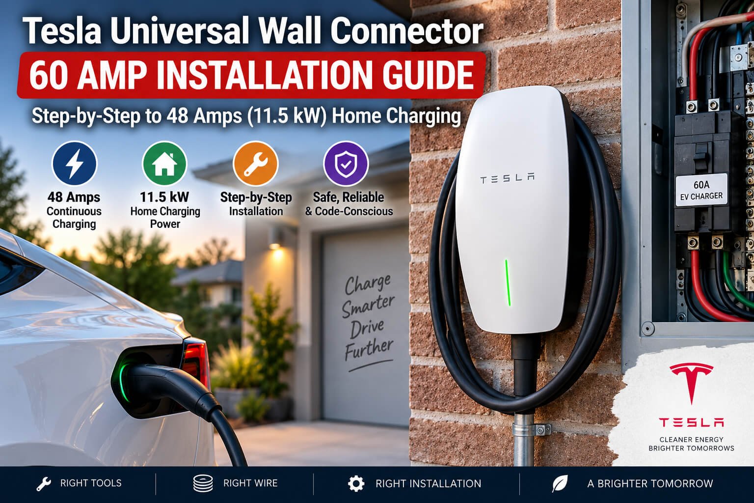
A Tesla Universal Wall Connector on a properly installed 60-amp circuit can deliver up to 48 amps continuously, or roughly 11.5 kW. That is a substantial amount of home charging power, and it makes day-to-day EV ownership much more convenient.
It is also serious electrical work. I am not an electrician, and this article is not a substitute for permits, local code requirements, qualified training, or the services of a licensed electrician. Electricity can injure or kill you, and a poor connection can create a fire risk long after the installation appears to be finished. Know your limits, verify the requirements in your jurisdiction, and bring in a qualified professional when appropriate.
Planning a faster and more convenient home charging setup?
What You’ll Learn
- A 60-amp circuit allows the Universal Wall Connector to charge continuously at 48 amps.
- Exterior conduit runs require conductors rated for wet and dry locations.
- Every panel, breaker, and charger terminal must be tightened to its specified torque value.
- QR code setup connects the charger through Bluetooth, firmware updates, and home Wi-Fi.
Table of Contents
- Why a 60 Amp Circuit Makes Sense for Tesla Home Charging
- Choosing Wire and Conduit for the Run
- Panel Work: Isolation, Grounding, and Torque
- Planning the Wall Penetration and Exterior Route
- Preparing and Mounting the Universal Wall Connector
- Connecting the Charger Conductors
- Configuring the Tesla Universal Wall Connector
- Testing the 48 Amp Charging Result
Why a 60 Amp Circuit Makes Sense for Tesla Home Charging
The Tesla Universal Wall Connector is designed to charge continuously at 48 amps when supplied by a 60-amp circuit. That follows the continuous-load principle: EV charging is not a quick, occasional load. It can run for hours, so the circuit needs enough headroom above the charging current.
In this case, the payoff is charging at around 11 to 12 kW at the vehicle. That is plenty of power for overnight charging and provides much more flexibility than a standard 120-volt outlet or a lower-capacity circuit.
Before buying wire or drilling holes, make sure the electrical service and panel have sufficient capacity for the added load. The charger circuit, breaker type, conductor selection, grounding method, conduit, weather exposure, and mounting location all need to work together. Tesla’s installation instructions should be part of the planning process, so keep the Tesla Universal Wall Connector installation manual close by.
Choosing Wire and Conduit for the Run
For this installation, there were two practical conductor approaches:
- 4/2 RX cable
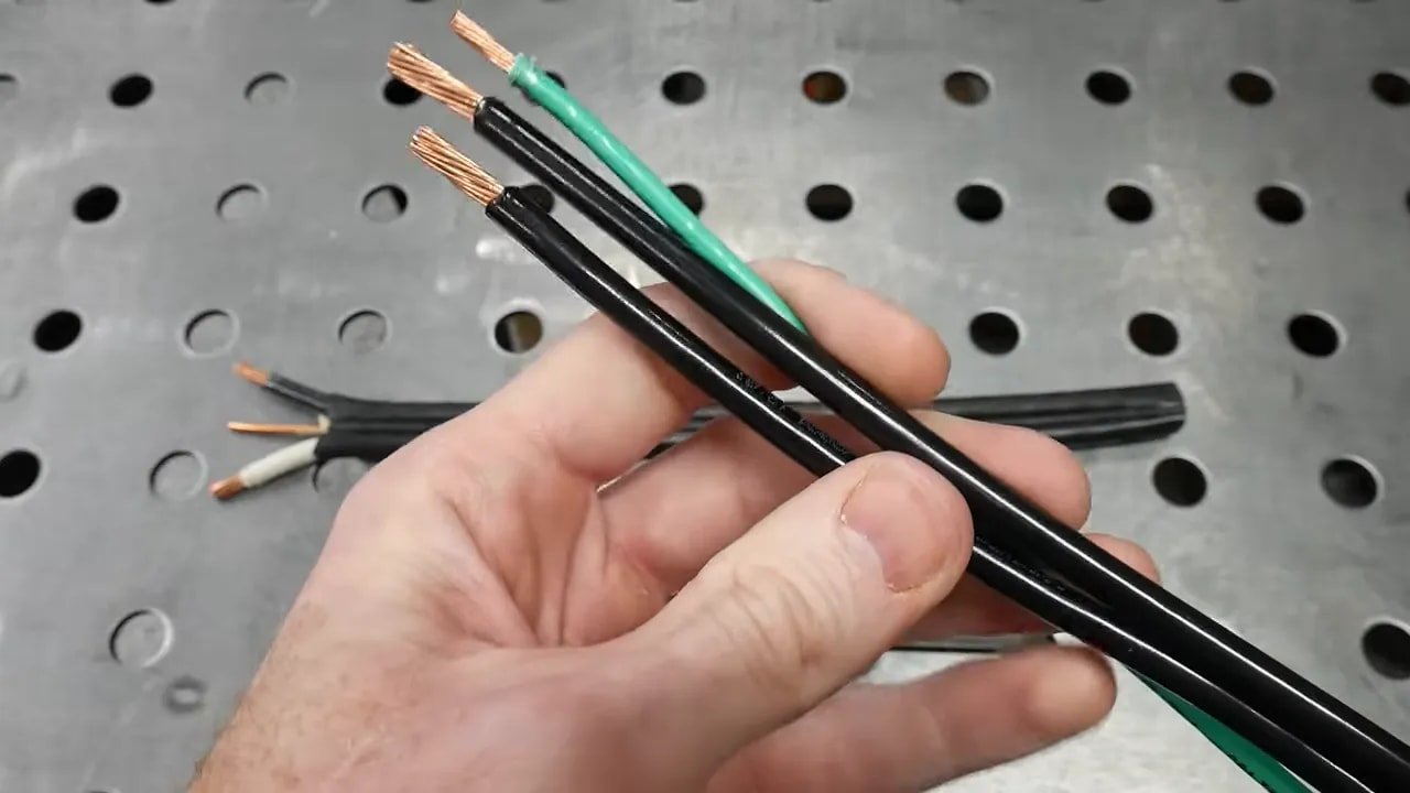
- Two 6 AWG THHN or THWN-2 stranded copper conductors in conduit, plus a 10 AWG THHN or THWN-2 copper ground
The route in this project exits the building to reach a charger mounted on an exterior brick wall. That makes conductor ratings especially important. Any wire installed in a wet-location pathway needs to be rated accordingly. THWN-2 can be used in wet or dry locations, and much of the THHN sold at major hardware stores is dual-rated as THHN/THWN-2. Still, do not assume. Read the markings printed on the wire.
RX cable may be workable for an interior run, but it is generally not appropriate to pull through exterior conduit. Besides being difficult to pull through conduit, it can conflict with electrical-code requirements when the run leaves the building. For this job, the choice was stranded 6 AWG THWN-2 copper for the two hot legs and a 10 AWG THWN-2 copper grounding conductor.
Conduit Sizing Matters
Three-quarter-inch Schedule 40 PVC has an inside diameter of about 0.824 inches. Based on conduit-fill tables, it can accommodate up to four 6 AWG THHN conductors. That makes it suitable for a two-hot-plus-ground EV charger run of this kind.
I already had one-inch conduit available, so the interior portion used one-inch PVC. The run then necked down to three-quarter-inch conduit for the passage through the wall and into the charger. The smaller conduit worked with the available strain-relief fitting and the hole through the brick.
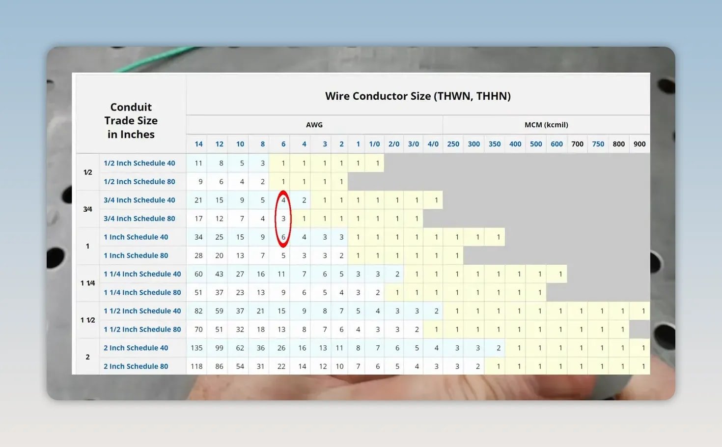
Do not treat conduit size as a guess. Conductor fill, bend count, pull difficulty, local code requirements, and the fittings at both ends all affect the final plan. A larger conduit is often easier to work with, especially when pulling heavy-gauge stranded copper.
Panel Work: Isolation, Grounding, and Torque
The subpanel was disconnected from the main panel before work began. That is a crucial step, but it does not automatically mean every portion of the electrical equipment is safe to touch. Verify that the equipment is properly de-energized and understand which components may remain energized.
A manual knockout punch created the correctly sized opening in the top of the subpanel for the one-inch conduit. The equipment ground was then connected to the subpanel’s ground bar, which is separate from the neutral bar. That separation is important in a subpanel.
Torque values are not optional details. The ground terminal in this panel called for 2.8 N·m, or 25 inch-pounds, for the 10 AWG ground conductor. The 60-amp breaker documentation called for 45 inch-pounds. The breaker conductors were torqued with the breaker outside the panel first, which helped avoid putting unnecessary stress on the panel bus blades during tightening.
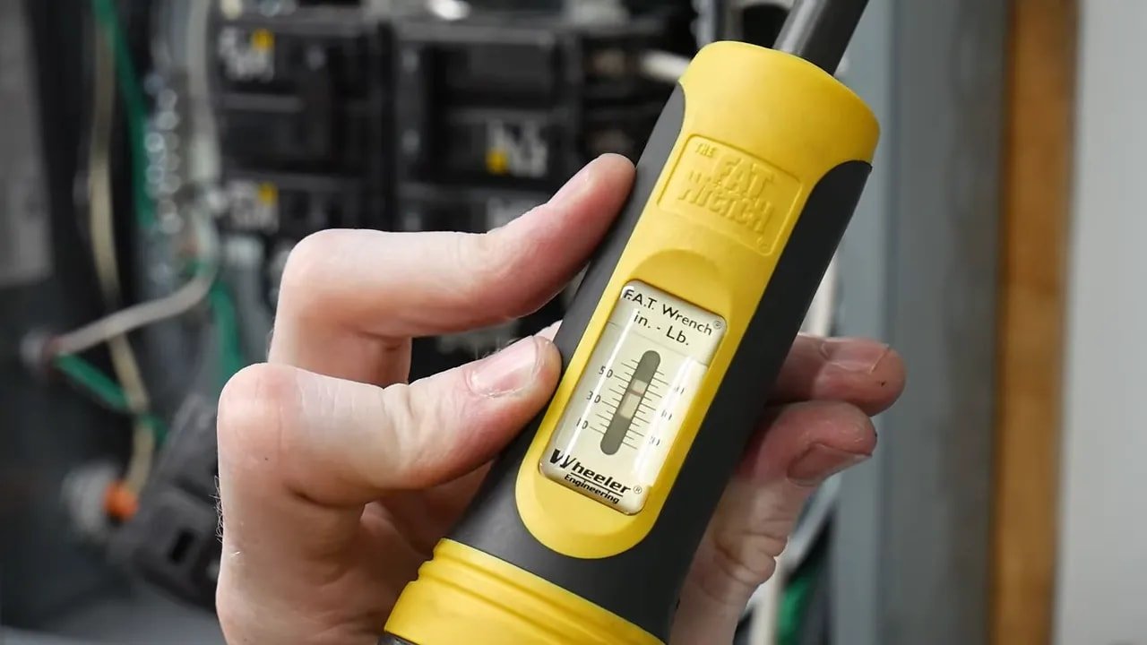
Loose electrical terminations create resistance and heat and can potentially lead to failure. Overtightening can damage hardware or conductors. Use a properly calibrated torque tool and follow the specific labeling and instructions for the equipment in front of you.
Planning the Wall Penetration and Exterior Route
The charger was going on the front-facing exterior garage wall, so the wall penetration had to line up with one of the lower rear cable-entry points on the Universal Wall Connector. The chosen entry point sits about one inch off the charger’s centerline.
After measuring the charger location, the exterior brick hole was marked at roughly 48 inches above the ground. A 1.6-inch outside-diameter core bit was used to pass through the brick and the interior wood backer. On the interior side, the drywall hole was located about half an inch higher than the brick opening. The reasoning was simple: if moisture ever entered around the penetration, the slope would encourage it to drain outward rather than inward.
The wall route used a three-quarter-inch conduit section, a reducer, a 90-degree LB conduit body, and strain-relief fittings. Some modification was needed to fit the reducer through the drywall opening, including grinding down a few points with a belt grinder.
Measure with the actual fittings in hand. The conduit path may look simple until the LB body, reducer, wall thickness, charger enclosure, and strain relief all start competing for the same fractions of an inch.
Preparing and Mounting the Universal Wall Connector
The charger comes in clean packaging with basic instructions and hardware. Before mounting, the designated mounting locations were drilled with a 3/16-inch bit. The lower rear entry point was opened with a step drill until it fit the three-quarter-inch conduit box adapter.
Take your time when opening the enclosure. It is easy to make a hole larger, but impossible to make it smaller again. Test-fit the adapter repeatedly and stop as soon as it seats properly.
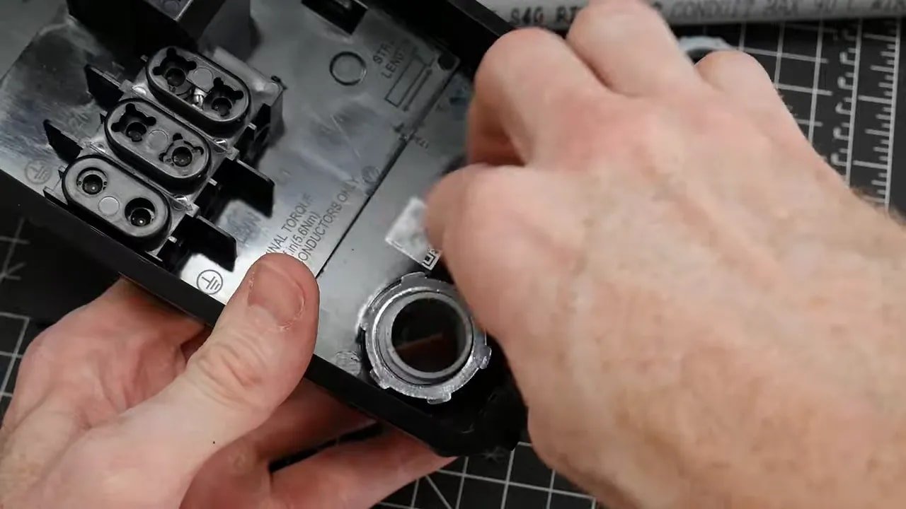
With the conduit fitting in place, the final through-wall conduit length could be measured accurately. The conduit was cemented into the fitting arrangement, and the charger was secured to the brick with 3/16-inch masonry anchors.
An expanding foam seal around the conduit was originally planned but did not make it into the final installation. The tight annular space between the conduit and brick did allow PVC adhesive to be applied around the joint. Exterior penetrations deserve close attention because managing water intrusion is every bit as important as getting the wire from point A to point B.
Want the Universal Wall Connector used for this type of home charging setup?
Connecting the Charger Conductors
Once the charger was mounted and the conduit was complete, the two 6 AWG hot conductors and the 10 AWG ground were pulled through and cut to length.
The wiring arrangement is straightforward:
- The two 6 AWG conductors land on L1 and L2.
- Because this is a 240-volt circuit, both of those conductors are hot legs.
- Either hot leg can go into either the L1 or L2 position.
- The grounding conductor lands on the ground terminal on the left side of the charger enclosure.
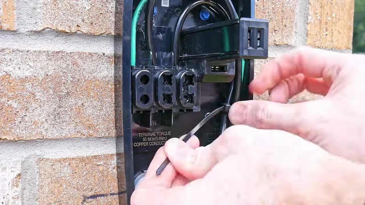
The Tesla-provided bit was used with a torque screwdriver to tighten the charger terminals to 50 inch-pounds, following the Universal Wall Connector manual. After the wiring was finished, silicone was applied around the enclosure edges, and the faceplate was installed.
This is the point to slow down rather than speed up. Confirm conductor seating, insulation clearance, terminal torque, grounding, strain relief, enclosure closure, and breaker compatibility before energizing anything.
Configuring the Tesla Universal Wall Connector
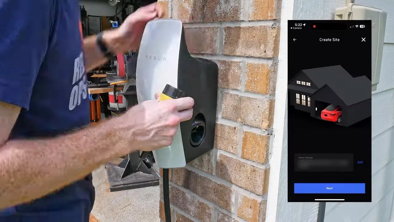
The software setup is refreshingly simple once the electrical work is complete. Scan the QR code sticker included with the charger. This initiates a Bluetooth connection between your phone and the Universal Wall Connector.
The sticker can then be placed on the 60-amp breaker in the panel. That gives you a convenient way to access the setup information later without having to search through packaging or paperwork.
From there, the charger updates its firmware and prompts you to connect it to your home Wi-Fi network. Wi-Fi connectivity allows the device to complete setup and remain connected for its intended smart features.
Testing the 48 Amp Charging Result
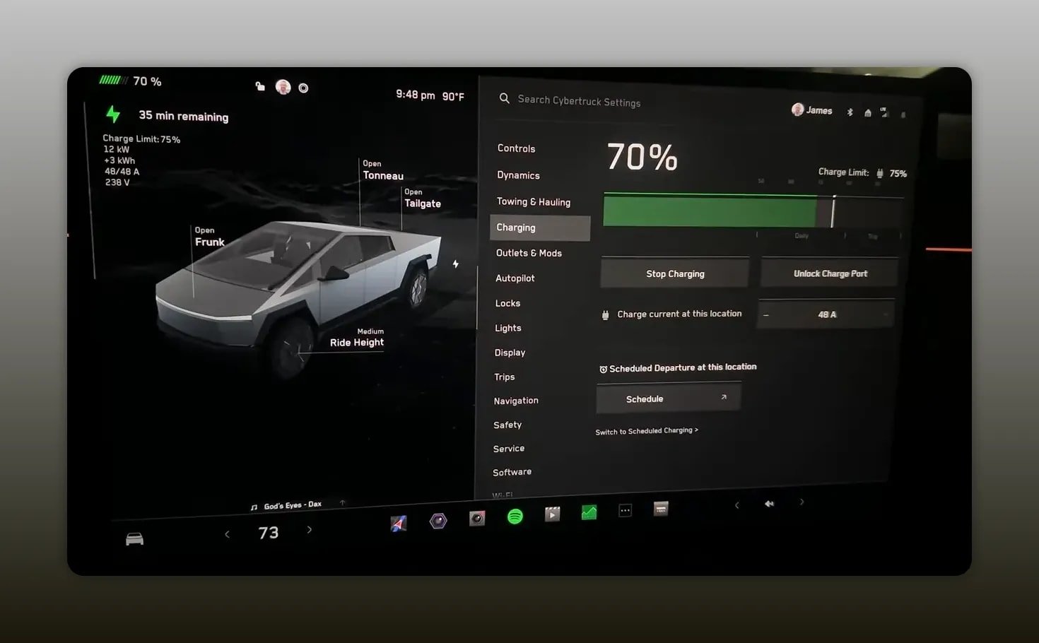
With the circuit energized and setup complete, the moment of truth came when the truck was plugged in. The charging display showed roughly 11 to 12 kW while drawing 48 amps, which is right where a 60-amp circuit and this wall connector should land.
The charger continued to work well through several weeks and a variety of weather conditions. The exterior mounting and cable routing also held up well, with water beading on the charger housing after rain.
A solid Tesla Universal Wall Connector installation is not about rushing to get a charging cable onto the wall. It is about choosing the right conductors, respecting conduit requirements, using the correct torque values, maintaining the proper ground and neutral arrangement in the subpanel, managing the exterior penetration, and verifying the result under load. Get those fundamentals right, and the convenience of fast home charging speaks for itself.
Ready to Upgrade Your Home EV Charging?
Check the Tesla Universal Wall Connector and current purchasing options on Amazon.
Related Guides
Frequently Asked Questions
Why does a Tesla Wall Connector need a 60-amp circuit for 48-amp charging?
EV charging is a continuous load. A 60-amp circuit provides the capacity for the charger to operate continuously at 48 amps.
What wire was used for this 60-amp Tesla charger installation?
This installation used two 6 AWG THWN-2 stranded copper hot conductors and one 10 AWG THWN-2 stranded copper grounding conductor in conduit.
Can the two hot wires be connected to either the L1 or L2 terminal?
Yes. On this 240-volt charging circuit, both L1 and L2 are hot legs, so either hot conductor can be placed in either terminal.
How much charging power did the installation provide?
The completed installation charged at about 48 amps and roughly 11 to 12 kW.