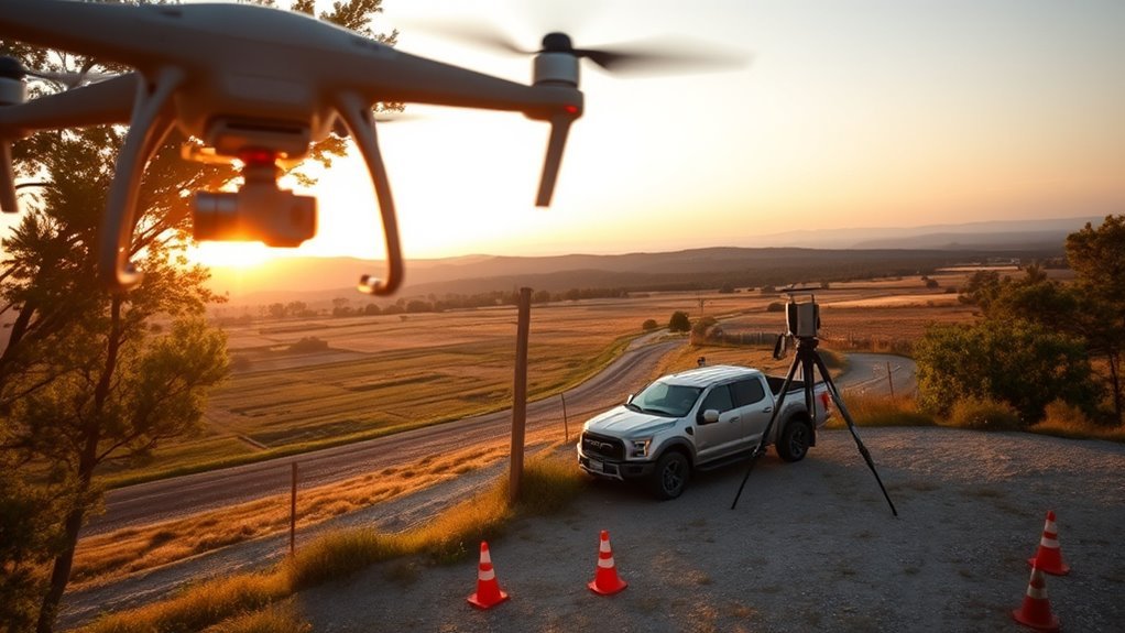
Drone mapping altitude directly shapes ground sample distance, which in turn affects detail, accuracy, and survey efficiency. Lower flights produce finer GSD and sharper measurements, while higher flights increase coverage but reduce resolution. Sensor size, focal length, and overlap settings all shift the outcome, so a calculator becomes useful before takeoff. The key question is not just how high to fly, but how high to fly for the target result.
What GSD Means for Drone Mapping
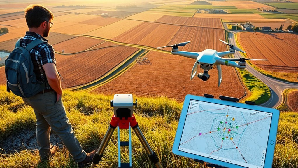
Ground Sample Distance (GSD) defines the real-world size represented by a single pixel in a drone image, making it a direct measure of spatial resolution in mapping missions.
In practical terms, GSD indicates how much ground detail each pixel can capture. A lower GSD means finer detail and sharper interpretation, while a higher GSD produces coarser results.
For mapping teams seeking operational freedom, this metric sets the limit of what can be measured, identified, and verified from the air.
GSD is calculated from sensor width, altitude, focal length, and image width in pixels, linking aircraft setup to image quality. It also influences positional accuracy; with sufficient Ground Control Points, horizontal accuracy is often estimated at about 1.5 times GSD.
As a result, GSD serves as a planning parameter for choosing equipment, flight settings, and survey objectives.
How Altitude Changes GSD
Altitude acts as a direct lever on Ground Sample Distance: as flight height increases, each pixel covers a larger ground area, so GSD rises and image detail declines. A doubling of altitude thus doubles GSD, reducing the ability to resolve edges, textures, and small features.
Higher altitude widens each pixel’s footprint, increasing GSD and reducing the fine detail you can resolve.
For precise mapping, lower altitude tightens GSD and improves model fidelity, but it also demands disciplined flight planning. The altitude required for a target GSD can be estimated as altitude = (target GSD × focal length) / pixel pitch, linking mission outcomes to measurable camera inputs.
- Higher altitude: broader coverage, coarser GSD
- Lower altitude: finer detail, lower GSD
- High GSD: critical features may vanish
- Target GSD: set altitude before launch
- Overlap: preserve coverage while holding resolution
Accurate altitude selection offers operational freedom by balancing speed, detail, and mission certainty without surrendering data quality.
Choose the Right Sensor and Lens
Sensor and lens selection determines whether a drone mapping mission can achieve the required GSD at a given flight altitude. Sensor width is a primary variable: a wider sensor can reduce GSD at the same height, improving map detail without lowering altitude.
Focal length also matters. Shorter lenses widen coverage but increase GSD, while longer lenses narrow the view and capture finer features. Image dimensions in pixels further refine results; higher pixel counts record more samples across the scene and support lower GSD.
Lens quality must not be neglected. A sharp, low-distortion optic preserves geometry and keeps models faithful to reality. The most effective setup matches sensor width, focal length, and pixel count to the planned altitude so overlap remains efficient and the mission stays free from unnecessary compromises.
In practice, the selected camera should be evaluated as a system, not as isolated parts, to deliver consistent mapping performance.
Estimate Horizontal and Vertical Accuracy
Horizontal and vertical mapping accuracy can be estimated directly from GSD and control-point placement. Ground Sample Distance (GSD) sets the base resolution: lower GSD yields tighter measurements and clearer freedom from uncertainty.
With four or more GCPs, horizontal accuracy is often about 1.5 times GSD, while vertical accuracy is roughly 2.5 times GSD. Without GCPs, those values can expand to about four times GSD horizontally and six times GSD vertically.
- Minimum GCP count: four
- Larger sites: add more control points
- Lower GSD: higher precision
- No GCPs: weaker positional confidence
- Proper flight altitude: match target GSD
This framework lets an operator estimate whether a mission can support surveying, inspection, or planning work.
The practical aim is simple: select altitude and control so the map measures terrain with dependable clarity, not guesswork.
Set Front and Side Overlap
Front overlap is typically set at 75% to 85%, with 80% to 85% preferred for complex 3D structures to improve capture consistency and stitching reliability.
Side overlap is commonly maintained at 60% to 70%, with 70% to 75% recommended when adjacent flight lines must align precisely.
Higher overlap improves data completeness and model quality, but it also increases flight time and storage demands, so the setting should balance coverage against efficiency.
Front Overlap Settings
When setting overlap for drone mapping missions, front overlap is typically configured between 75% and 85% to guarantee adequate image capture and reliable stitching.
In practice, 80% to 85% is preferred for 3D modeling, where fine terrain detail must be preserved without compromise. Lower values risk gaps, weak tie points, and reduced map accuracy; higher values increase battery demand and processing time.
The photo interval should be tuned to hold the selected front overlap at the planned speed and altitude.
- 75% for efficient orthomaps
- 80% for balanced accuracy
- 85% for detailed 3D capture
- Shorter intervals at faster flight speeds
- More overlap, more power required
Side Overlap Settings
Side overlap, or sidelap, defines the percentage of overlap between adjacent flight lines and is essential for linking imagery across the survey area.
For mapping missions, side overlap of 60-70% is generally recommended because it supports reliable tie points and consistent coverage. If side overlap is too low, gaps may appear and image stitching can fail, reducing map integrity.
For 3D modeling, especially in dense urban zones, 70-75% side overlap helps reduce occlusion and improves capture of vertical features. Higher values increase image volume, which raises processing time and storage demands.
A deliberate side overlap setting gives operators practical control over data completeness and workflow efficiency, supporting accurate, independent surveying without unnecessary constraint.
Overlap Balance Tradeoffs
Balancing front and side overlap requires matching coverage needs with flight efficiency, since a front overlap of 75-85% and a side overlap of 60-70% generally provides reliable mapping results. This overlap balance protects accuracy while preserving battery, storage, and field time for liberated, efficient surveying.
- Higher overlap improves stitching reliability.
- Over 90% front overlap increases flight time.
- Low overlap risks gaps and poor alignment.
- 3D urban work benefits from 80-85% front and 70-75% side overlap.
- Photo interval = (Footprint Height × (1 – Overlap%)) / Flight Speed.
Proper overlap settings support complete image capture across flight lines, reducing occlusion and enabling cleaner models.
Calculate Flight Lines, Photos, and Time
Calculating flight lines, photos, and mission time requires matching the survey area, overlap settings, and aircraft speed to the planned ground coverage. The number of flight lines depends on swath width and overlap; higher overlap reduces gaps but increases line count, tightening control over the map grid.
Total photos are estimated from flight distance and photo spacing, then multiplied by the number of flight lines: Total Photos = (Flight Distance / Photo Spacing) × Number of Flight Lines. Because photo spacing shrinks as overlap rises, image volume increases quickly.
Mission time follows total distance and cruise speed: Flight Time (minutes) = Total Distance (km) / Flight Speed (km/h). This framework supports efficient, autonomous coverage while preserving survey freedom from unnecessary passes.
Lower GSD values capture finer detail, so planning must align data quality with available time and battery budget. Flight lines, photos, and time should be verified before launch to prevent undercoverage or wasted sorties.
Calculate Altitude for a Target GSD
A target Ground Sample Distance can be converted to flight altitude with the relation altitude = (target GSD × focal length) / pixel pitch, linking sensor geometry directly to mapping scale.
Because pixel pitch and focal length determine how altitude translates into GSD, higher flight heights produce coarser resolution and lower heights produce finer detail.
Effective planning also requires maintaining suitable overlap, since altitude changes alter both image coverage and the horizontal and vertical accuracy of the resulting map.
Target GSD Formula
To determine the flight altitude required for a target Ground Sample Distance (GSD), the relationship is expressed as altitude = (target GSD × focal length) / pixel pitch, where pixel pitch is obtained by dividing sensor width by image width in pixels.
This target GSD formula gives operators a direct, liberated path to predictable mapping outcomes.
- Set the desired GSD first.
- Insert focal length from the camera.
- Compute pixel pitch from sensor and image size.
- Expect lower altitude to reduce GSD and sharpen detail.
- Expect doubled altitude to double GSD and reduce resolution.
Practical execution also demands stable overlap, typically 75-80% front and 60-70% side, so coverage remains reliable while accuracy stays high.
Altitude And Pixel Pitch
When a target GSD is known, the required flight altitude can be derived from the camera’s focal length and pixel pitch using altitude = (target GSD × focal length) / pixel pitch. Pixel pitch sets the sensor’s sampling scale, so smaller pixels usually permit lower altitude for the same GSD. Since GSD rises as altitude rises, operators seeking finer detail must reduce altitude accordingly. The relationship is direct, predictable, and practical for mapping missions that demand liberated, precise measurement.
| Variable | Effect on altitude |
|---|---|
| Larger pixel pitch | Higher altitude required |
| Smaller pixel pitch | Lower altitude required |
A lower GSD means higher resolution, supporting detailed imagery and accurate surface measurement. Ideal altitude is thus a controlled choice, not a guess.
Accuracy Planning Tips
For precise altitude planning, the target GSD is converted into flight height using altitude = (target GSD × focal length) / pixel pitch, allowing operators to match image resolution to survey requirements.
These accuracy planning tips keep GSD tied to mission intent, not guesswork.
- Fly lower when finer detail is needed.
- Expect doubled altitude to double GSD.
- Keep front overlap at 75–80%.
- Keep side overlap at 60–70%.
- Use four or more GCPs for 1.5× GSD horizontal accuracy.
This framework gives crews freedom to scale coverage and detail deliberately. A lower flight altitude sharpens output, while controlled overlap and ground control preserve measurement reliability.
The result is disciplined mapping that stays accurate, efficient, and usable across varied terrain.
See a Drone Mapping Example
A practical drone mapping example begins with altitude selection, since height directly determines GSD and, in turn, image detail. In Drone Mapping, a 100-meter flight commonly produces about 2.5 cm GSD, which supports precision surveys and fine feature extraction. That relationship can be estimated with altitude = (target GSD × focal length) / pixel pitch, allowing the mission to be set before launch.
| Parameter | Example |
|---|---|
| Altitude | 100 m |
| GSD | 2.5 cm |
| Front / Side Overlap | 75–80% / 60–70% |
| Accuracy with GCPs | ~1.5× GSD |
With four or more GCPs, horizontal accuracy can tighten to roughly 1.5× GSD, versus about 4× GSD without them. This setup gives operators greater freedom: the mapped surface becomes measurable, repeatable, and fit for demanding field decisions.
Avoid Common Altitude and GSD Mistakes
Altitude selection must be matched to the target GSD, because higher flights increase GSD proportionally and reduce image resolution. Misjudging altitude can erode mission freedom: too high, and detail is lost; too low, and flight time and battery demand rise.
The altitude formula, altitude = (target GSD × focal length) / pixel pitch, should guide planning, not guesswork.
- Keep front overlap at 75-85% for continuous coverage
- Keep side overlap at 60-70% to preserve edges
- Use four or more GCPs to reach about 1.5× GSD accuracy
- Avoid excessive overlap caused by unnecessarily low altitude
- Avoid gaps caused by altitude that is too high
These settings help prevent incomplete data, wasted sorties, and unstable deliverables. A disciplined altitude choice aligns GSD, overlap, and control points, producing cleaner maps and more autonomous decision-making.
Frequently Asked Questions
What Is a Good GSD for Drone Mapping?
A good GSD for drone mapping is typically 2.5 cm to 5 cm per pixel. For high-detail work, 2.5 cm is preferred; for general mapping, 5 cm is often sufficient.
GSD Importance lies in its direct effect on horizontal and vertical accuracy, especially when paired with four or more GCPs.
Proper overlap, about 75–85% front and 60–70% side, helps capture liberated, reliable mapping data.
What Is the 1:1 Rule for Drones?
The 1:1 rule says a drone should fly at an altitude numerically equal to the desired GSD, so a 5 cm GSD pairs with roughly 5 m height—why overcomplicate precision?
This Altitude Impact keeps pixel scale predictable, improving measurement fidelity, mapping detail, and practical field control.
It remains a guideline, not an absolute law, because camera specs, terrain, and overlap settings can require adjustment for ideal, liberated survey workflows.
How Accurate Is Drone Mapping?
Drone mapping is typically accurate to about 1.5× GSD horizontally and 2.5× GSD vertically when four or more GCPs are used; without GCPs, error can rise to 4× and 6× GSD.
Accuracy depends on altitude, sensor geometry, focal length, image size, and overlap.
Strong Data Reliability requires disciplined flight planning, proper control points, and sufficient front and side overlap, enabling practical, liberated decision-making from trustworthy spatial data.
How to Calculate Flying Height?
Flying height is calculated by altitude = (target GSD × focal length) / pixel pitch.
Altitude Considerations require knowing sensor width and image dimensions to derive pixel pitch accurately.
Because GSD scales linearly with altitude, doubling height doubles ground resolution.
For high-detail mapping, a 1–2 cm GSD is typical.
Validation should use 75–85% front overlap, 60–70% side overlap, and 4+ GCPs to confirm 1.5× GSD accuracy.
Conclusion
In drone mapping, altitude and GSD must be matched to the required accuracy, sensor, and overlap settings. Lower flight heights improve detail and reduce GSD, while higher altitudes increase coverage but reduce resolution. With a calculator, the right balance can be set before takeoff, improving efficiency and survey reliability. Why guess at flight height when the target GSD can be calculated directly? Careful planning helps avoid missed detail, weak accuracy, and unnecessary rework.
