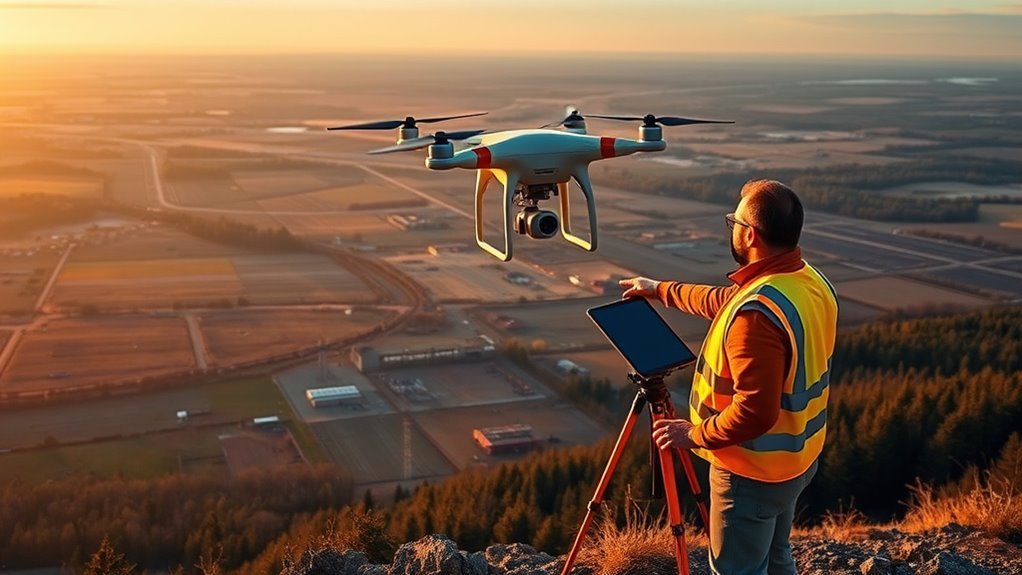
Drone mapping overlap settings determine how much image redundancy is built into a flight plan, with front overlap and side overlap serving different roles in model continuity and coverage. Standard values often start near 70% front and 60% side, yet terrain, structures, altitude, and lighting can shift the ideal balance. The real question is not what default to use, but when higher overlap becomes necessary and what it changes in the final product.
Front vs. Side Overlap Explained
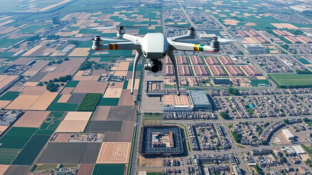
Front overlap refers to the amount of shared area between consecutive images captured along the drone’s flight path, while side overlap describes the shared area between adjacent flight lines. In drone mapping, this image overlap is not interchangeable; each parameter governs a different axis of coverage and directly affects reconstruction reliability.
Front overlap supports longitudinal continuity, helping software match features between sequential frames. Side overlap strengthens lateral continuity, reducing striping and gaps between passes. Together, they form the geometric basis for stable photogrammetric outputs.
Higher overlap percentages improve tie point density, increase stitching accuracy, and support cleaner map generation. Insufficient overlap can weaken alignment and leave unresolved voids, limiting spatial detail and user control.
Terrain complexity, flight altitude, and project goals can require adjustment, but the distinction remains constant: front overlap preserves continuity along track, while side overlap preserves continuity across track, enabling more complete and liberated data capture.
Recommended Overlap for Orthomosaics
For orthomosaic mapping, baseline overlap targets are typically set at 70% front overlap and 60% side overlap to support reliable image stitching and data recovery.
In urban or otherwise complex environments, increasing front overlap to about 85% and side overlap to 75–80% improves feature continuity and reduces gaps in the map.
This redundancy guarantees that each ground point is recorded in multiple frames, which directly strengthens processing stability and final map accuracy.
Baseline Overlap Targets
Baseline overlap targets for orthomosaic mapping typically begin at 70% front overlap and 60% side overlap, providing sufficient image redundancy for reliable stitching, complete ground coverage, and stable downstream processing.
These baseline recommendations support consistent feature matching in photogrammetry software, reducing gaps and limiting geometric distortion across the mosaic. The front overlap preserves longitudinal continuity along flight lines, while side overlap strengthens cross-track tie points and improves alignment confidence.
Where terrain complexity increases or vegetation occludes the surface, higher capture density may be warranted, but the baseline remains a practical starting point for most projects.
Flight planning software can formalize these settings, translating operational intent into repeatable data acquisition. In effect, disciplined overlap selection enables more dependable orthomosaic outputs and greater analytical independence.
Urban Area Adjustments
Urban orthomosaic projects typically require higher image redundancy, with at least 80% front overlap and 70% side overlap to preserve detail and reduce occlusion from tall buildings.
In urban areas, these overlap settings support cleaner mosaics by limiting shadow breaks and facade loss. When building heights vary considerably, front overlap may be raised to 85%, while side overlap often moves to 75-80% to maintain continuous coverage across narrow corridors and obstructed streets.
Heavily vegetated districts benefit from 85/80 settings, improving capture in mixed canopies and built forms. An 80/80 configuration is also practical where operational freedom requires fewer repeat flights.
These overlap settings reflect a technical balance: enough redundancy to map complex city surfaces accurately, without imposing unnecessary flight time or mission complexity.
Redundancy For Accuracy
Orthomosaic workflows rely on high redundancy to preserve completeness and mapping fidelity, with 80% front overlap and 80% side overlap commonly recommended as a practical standard.
In Drone Photogrammetry, this overlap increases accuracy by ensuring multiple images observe each ground point, strengthening tie-point extraction and seam placement. The result is a denser, more resilient dataset that reduces data gaps and mitigates occlusions from buildings, trees, and other urban obstructions.
Higher redundancy also improves stitching reliability, lowering the likelihood of re-flights and unnecessary constraint on field operations.
Where terrain complexity or project requirements differ, overlap settings can be adjusted to balance capture efficiency with model quality, supporting rigorous analysis while maintaining operational autonomy and clearer spatial truth.
Adjust Overlap for Terrain and Buildings
Adjusting overlap becomes essential when terrain complexity or building height increases, because standard flight settings may leave gaps in roof detail, façades, or uneven ground. Effective overlap between consecutive images depends on site relief, object height, and camera altitude.
On uneven terrain, front overlap often rises to 85%, with side overlap near 80%, preserving continuity where elevation changes rapidly. Tall urban structures may require 80–85% front overlap to secure rooftop and façade coverage. Flat sites can often retain 70% front and 60% side, provided local features remain modest.
Flight planning software should be used to evaluate these variables before launch and to avoid under-sampling.
- Steeper relief demands denser sampling
- Taller buildings reduce rooftop visibility
- Higher altitude may still miss upper surfaces
- Software can tune settings per sector
- Site-specific checks prevent data voids
Use Higher Front Overlap for 3D Models
Higher front overlap is critical for 3D modeling because it increases image redundancy across forward motion, improving feature matching and reducing reconstruction gaps.
Coverage gains are most evident in complex terrain and urban scenes, where 80–85% overlap supports denser point clouds and fewer occlusions.
For detailed outputs, 80% is a practical baseline, while 85% is preferable when flight altitude, terrain variability, and model accuracy requirements are more demanding.
Why Front Overlap Matters
Front overlap, or frontlap, plays a critical role in 3D drone mapping by ensuring consecutive images share enough common ground points for accurate reconstruction. Higher front overlap supports precise feature matching in overlapping images, which is essential for stable 3D modeling across complex scenes and urban environments.
- 80–85% is recommended for demanding models
- More redundancy improves stitch reliability
- Occlusions are easier to resolve
- Uneven terrain retains finer detail
- Data gaps are reduced in reconstructions
This setting grants the model enough repeated visual evidence to constrain geometry without ambiguity.
In practice, elevated front overlap strengthens the analytical integrity of the output, allowing surveyors to capture structure, surface variation, and spatial relationships with greater technical confidence.
3D Model Coverage Gains
For 3D mapping workflows, a front overlap setting of 80–85% materially improves model coverage by ensuring that successive images capture the same ground features from multiple viewpoints.
This higher front overlap increases redundancy, which supports robust image matching where occlusions or irregular surfaces would otherwise interrupt continuity. In complex terrain and urban scenes, the added coverage reduces gaps and strengthens stitching accuracy, producing smoother transitions between frames.
The result is a denser point cloud and a more reliable surface reconstruction. Maintaining at least 80% front overlap helps preserve geometric continuity, while 85% can further improve the final output for high-resolution projects.
Such settings give mapping operators greater technical autonomy over data completeness and model integrity without unnecessary acquisition risk.
Best Settings For Detail
Detailed 3D models typically require a front overlap of 80–85% to preserve feature continuity and support accurate image matching across successive frames. Higher front overlap increases redundancy, yielding adequate image coverage and reducing data gaps in complex terrain.
It also improves stitching, allowing dense point clouds to form with fewer matching errors.
- 80–85% front overlap for detail
- More redundancy, fewer voids
- Better handling of occlusions
- Stronger shadow resilience
- Adjust drones flight path to project requirements
When project requirements demand precision, the drones flight path should prioritize consistent forward sampling over speed. This approach supports accurate feature reconstruction, enabling liberated mapping workflows where detail is not sacrificed for efficiency.
How Altitude Changes Effective Overlap
Altitude directly changes effective overlap because the higher the flight level, the smaller each image’s ground footprint becomes relative to vertical relief, which can reduce true coverage over tall terrain and structures. In practical terms, an 80% overlap at 80 meters may not preserve equal effective coverage over a 40-meter building. As altitude rises, overlap often needs a 10-15% increase to protect data quality, especially in urban environments. Lower altitudes can tolerate less overlap; higher altitudes usually cannot.
| Altitude condition | Effect on overlap |
|---|---|
| Low altitude | Lower overlap may suffice |
| Moderate altitude | Standard overlap remains acceptable |
| High altitude | Increase overlap 10-15% |
| Tall structures | Effective coverage decreases |
| Variable terrain | Recalculate overlap per feature |
Terrain height and building height must thus guide flight design. Precise altitude selection supports complete mapping, minimizes gaps, and preserves reliable reconstructions.
Adjust for Weather and Lighting
Even after altitude and terrain have been calibrated, weather and lighting can still alter usable coverage and image quality. In drone mapping, operators should adjust overlap settings when weather conditions degrade stability or visibility, preserving data continuity and the freedom to work with reliable imagery.
- Strong winds, rain, or fog may require a 5–15% increase in overlap settings.
- Shadows from buildings or trees can justify 10–15% more front overlap in cities.
- Bright sunlight can burn highlights, so lighting conditions must be monitored and camera settings tuned.
- Dense vegetation often needs about 85% front and 80% side overlap.
- Forecast checks before flight help plan when to adjust overlap and reduce loss.
These adjustments are not optional refinements; they are control measures that protect image quality, limit gaps, and keep mapping outputs defensible across changing environments.
Use GCPs for More Reliable Maps
Ground Control Points (GCPs) are used to anchor drone imagery to precise ground locations, improving positional accuracy and supporting sub-inch mapping results.
In practice, Ground Control Points distribute control across the site, allowing overlap guarantees each marker is captured in 5-10 images for robust tie points. This reduces dependence on onboard GPS, whose error can vary sharply in urban canyons, near structures, or over uneven terrain.
For mapping projects requiring defensible measurements, GCPs should be placed evenly, with extra control at edges and elevation changes to constrain distortion. Proper overlap planning is still necessary, because poor coverage can create gaps, blur, or weak point clouds that undermine positional accuracy.
When combined with disciplined flight paths, GCPs make the dataset more independent of machine uncertainty and more responsive to ground truth. The result is a map that serves accurate decision-making and supports liberated field workflows.
Frequently Asked Questions
Is PPK or RTK More Accurate?
PPK is generally more accurate, though RTK can match it under ideal conditions.
In accuracy comparisons, PPK advantages arise from post-processed base-station corrections that better absorb outages, multipath, and time-sync errors.
RTK limitations include dependence on continuous communication and immediate solution quality.
Application scenarios favor RTK for rapid field feedback, but PPK for larger or complex surveys where liberated, robust centimeter-level precision matters most.
What Are the Best Settings for Drone Photography?
80/80 overlap can reduce re-flights by nearly half in complex missions, a practical statistic with real operational value.
The best settings for drone photography depend on camera settings, lighting conditions, altitude adjustments, and lens selection. A detached operator would prioritize low ISO, manual shutter control, and matched white balance, then tune exposure for scene contrast.
Higher overlap and consistent altitude preserve detail, enabling reliable stitching and technical freedom.
What Is the Best Mapping Software for Drones?
The best mapping software for drones depends on mission goals, but Pix4D is often the strongest technical choice. It combines advanced mapping software tools, broad compatibility options, and detailed photogrammetry control.
DroneDeploy offers a cleaner user interface and faster cloud workflows, while Agisoft Metashape excels in precision and cost analysis for high-resolution outputs.
Selection should prioritize autonomy, data quality, and operational freedom over branding or convenience.
What Is the Purpose of Longitudinal Overlap in Photogrammetry?
Longitudinal overlap exists to make adjacent frames redundantly witness the same ground, which, ironically, limits confusion by creating certainty. It improves longitudinal overlap benefits, supports ideal overlap ratios, and enables overlap impact analysis for aerial imagery precision.
In photogrammetry, this redundancy strengthens stitching, reduces occlusions, and stabilizes 3D reconstruction. Higher values increase reliability over complex terrain, granting practitioners more control and methodological freedom in demanding survey conditions.
Conclusion
In drone mapping, front and side overlap should be treated as project-specific variables rather than fixed defaults. A baseline of 70% front and 60% side overlap is often adequate for orthomosaics, but complex urban blocks, dense vegetation, or 3D reconstruction commonly require 80%/70% or higher. For example, a hypothetical survey of a mixed forest and building site would benefit from increased overlap and GCPs to reduce gaps and improve model reliability.