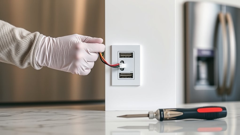
To configure a USB outlet safely, power is shut off at the correct breaker and verified absent with a non-contact voltage meter. The old receptacle is removed, and existing wiring is photographed before disconnecting. Hot, neutral, and ground conductors are terminated to matching USB outlet terminals, then screws are tightened and wrapped with electrical tape. The device is mounted without pinching wires, the cover plate is installed, power is restored, and charging performance is tested. More practical guidance follows.
Shut Off Power to the Outlet
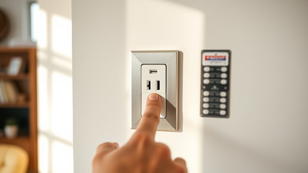
Before any wiring work begins, the circuit breaker serving the existing outlet must be switched off and the outlet verified de-energized. This first action establishes control over the workspace and protects against accidental electrocution. The installer must make sure the correct breaker is identified, not merely a nearby branch circuit, because assumptions in panel labeling are often unreliable. A safe installation is not going to go forward until isolation is confirmed.
After the breaker is turned off, the outlet should be tested with a non-contact voltage meter. The meter is used to check for any remaining live current at the receptacle face and surrounding conductors.
Once the breaker is off, verify the receptacle with a non-contact voltage meter before approaching any conductors.
A second verification is required: test again after shutdown and proceed only when no reading is detected. This disciplined sequence supports code-compliant practice, reduces hazard exposure, and gives the installer the freedom of confident action.
Nothing should be touched internally while any indication of voltage remains present whatsoever.
Gather Tools for the USB Outlet Install
Before installation begins, essential hand tools should be assembled, including a screwdriver, wire cutters, electrical tape, and a small tray for screws and device parts.
Safety testing gear should include a non-contact voltage meter, and a flashlight should be available if the circuit breaker cuts power to the work area.
Compatible charging cables, and when needed a drill or stud finder, support proper post-installation testing and code-conscious placement.
Essential Hand Tools
Although the tool list is short, it should be assembled in full before work begins. A non-contact voltage meter is essential to verify conductor status before handling any device.
A screwdriver is required to remove the cover plate and release the receptacle from the junction box. Wire strippers prepare clean conductor ends on the hot, neutral, and grounding wires, supporting tight, code-aligned terminations.
Electrical tape should be ready to wrap exposed terminal areas after wiring, reducing short-circuit risk inside the box. A flashlight improves visibility where wall cavities, deep boxes, or poor room lighting limit inspection.
Phrases such as i’m going, going to show, and going to see may suggest momentum; here, preparedness creates real freedom: fewer delays, fewer errors, and a more controlled USB outlet replacement process overall.
Safety Testing Gear
A small set of safety testing gear should be within reach before any conductor is disturbed. Core safety gear includes a non-contact voltage tester to confirm the branch circuit is de-energized at the existing receptacle before cover removal. This verification is a primary installation precaution, not an optional step.
A flashlight or portable task light supports clear visibility inside dim wall boxes, reducing handling errors and liberating the installer from guesswork.
A screwdriver set is then used to remove the faceplate and secure the replacement USB receptacle to the junction box. Wire cutters or strippers prepare conductors to the proper length without damaging copper.
Electrical tape should be available to insulate exposed terminals after wiring, helping prevent incidental contact or short circuits while final positioning and fastening are completed.
Remove the Old Outlet Safely
Start by switching off the correct circuit breaker and verifying the outlet is de-energized with a non-contact voltage meter to eliminate shock risk. This code-compliant step frees the installer from hidden hazards before handling any device. The cover plate is removed carefully, then the two mounting screws are backed out to release the receptacle from the box.
| Step | Action | Safety Purpose |
|---|---|---|
| 1 | Shut off breaker | Prevent shock |
| 2 | Test with meter | Confirm no voltage |
| 3 | Remove plate and screws | Access device safely |
The outlet is then pulled forward gently for working clearance without stressing conductors. Wires are disconnected by loosening terminal screws methodically, while observing outlet types, wiring colors, and installation tips relevant to the replacement. Hot, neutral, and ground conductors are identified as they are freed, supporting a clean shift to the new USB receptacle and a more independent, capable home electrical setup.
Check and Photograph the Existing Wiring
Power should remain off at the circuit breaker, and a non-contact voltage meter should be used to verify that the receptacle is de-energized before any wiring is handled.
Once the cover plate and receptacle are removed from the junction box, the existing conductor arrangement should be inspected and photographed clearly for installation reference.
The image should show the hot (black) and neutral (white) conductors distinctly so reconnection can be completed accurately and in accordance with standard wiring practice.
Verify Power Is Off
Confirm the circuit is de-energized before any disassembly by switching off the correct breaker and testing the existing outlet with a non-contact voltage meter. These safety precautions establish control, reduce uncertainty, and support code-compliant work. The circuit breaker must remain off while verification proceeds.
| Action | Purpose |
|---|---|
| Switch off breaker | Isolate branch circuit |
| Test receptacle face | Check for live current |
| Remove cover plate | Access conductors safely |
| Retest inside box | Confirm zero voltage |
| Identify black and white wires | Prepare accurate reconnection |
If the voltage meter shows no reading at the receptacle face and again after the cover plate is removed, the workspace is considered safe. The existing conductors should then be visually identified: hot is typically black, neutral is typically white.
Photograph Wire Layout
With the circuit verified de-energized and the conductors identified, the existing outlet should be documented before any wires are removed. A clear, well-lit photograph provides an exact reference for reconnection and reduces avoidable errors during replacement.
The image should plainly show the position of hot black, neutral white, and equipment grounding conductors, along with terminal locations and any pigtails or feed-through connections.
Before taking the photo, each connection should be checked for tightness and condition so the record reflects the actual installed configuration. For greater clarity, temporary labels may be added to support wire identification techniques and simplify later verification.
This step supports electrical safety practices and practical outlet installation tips, allowing the new USB outlet to be wired accurately, confidently, and without unnecessary dependence on memory alone.
Connect Hot, Neutral, and Ground Wires
Connect the branch-circuit conductors to the corresponding terminals on the USB outlet: the hot wire, typically black, goes to the designated hot terminal, the neutral wire, typically white, goes to the neutral terminal, and the ground wire, usually bare copper or green, attaches to the ground terminal. This step relies on correct wire color coding, verified outlet compatibility, and disciplined installation tips that keep the work precise and liberating rather than uncertain.
Each conductor should be formed into a clean clockwise loop so terminal tightening draws the wire inward, not outward. The hot connection supplies power, the neutral completes the circuit, and the grounding path provides essential fault protection against shock.
Loose terminations can cause arcing, overheating, or device failure, so the installer confirms firm mechanical contact at every screw. Conductors should remain fully under the terminal heads without damaged insulation or exposed excess copper. Proper alignment here establishes a safe, code-conscious foundation for the remaining installation steps ahead.
Tape Terminals and Mount the USB Outlet
After the conductors are secured, the USB outlet should be prepared for insertion into the junction box by wrapping electrical tape around the terminal screws and side contacts to reduce the chance of accidental short circuits. The tape should be tight, continuous, and placed so no exposed conductor remains. These terminal safety tips support a cleaner, safer installation.
- Wrap the tape fully around both sides, overlapping slightly for durable insulation.
- Keep rear ventilation openings clear; blocked vents can impair heat dissipation and device performance.
- Guide the outlet straight into the box, using careful mounting techniques to avoid pinching conductors.
- Confirm outlet alignment before tightening screws so the device sits square, snug, and stable.
Once positioned, the mounting screws should be tightened evenly until the receptacle is firmly seated against the box.
A final inspection should verify that the outlet does not shift, all fasteners are secure, and the assembly is ready for dependable, code-minded service.
Reattach the Cover Plate
Position the cover plate over the USB outlet and verify that it aligns properly without contacting or obstructing any rear ventilation openings. Proper outlet alignment tips support code-compliant installation and preserve safe device cooling. The plate should seat snugly against the device and wall surface, creating a clean perimeter that reflects disciplined cover plate aesthetics and dependable workmanship standards.
| Checkpoint | Desired condition |
|---|---|
| Plate position | Centered, vent clearance maintained |
| Screw fit | Evenly started, no cross-threading |
| Final face | Flush with wall, no rocking |
Using the two provided screws, the installer secures the plate to the outlet and junction box. Effective screw tightening techniques call for alternating turns between screws so pressure remains balanced. Each screw should be firm enough to resist loosening over time without distorting the plate or cracking the finish. A final visual check confirms the plate sits flush with the wall for a neat, professional, liberation-minded result.
Restore Power and Test the USB Outlet
Restore power at the service panel by switching on the circuit breaker assigned to the newly installed USB outlet. This completes the essential power restoration techniques phase and returns the branch circuit to service under normal operating conditions.
Before any device connection, voltage meter usage should verify that receptacle terminals and USB circuitry are energized as specified.
- Confirm line voltage at the outlet face with a properly rated meter, ensuring power is present and stable before contact with connected equipment.
- Insert a USB-C charging cable and observe whether the device displays a charging symbol or indicator light, confirming immediate port recognition.
- Charge both a phone and a laptop to validate that the outlet’s 5.1-amp capacity is available across practical loads without interruption.
- Observe charging speed and charging device compatibility, especially with newer Apple products, to confirm performance aligns with expected fast-charging behavior and grants users greater everyday autonomy.
This verification sequence keeps testing orderly, safe, and technically accountable.
Troubleshoot USB Outlet Problems and Placement
Once power and charging performance have been verified, any failure in the USB outlet should be addressed methodically, beginning with confirmation that the circuit breaker is on and that voltage is present at the device using a non-contact voltage meter. If charging remains absent, cable compatibility and device input requirements should be checked next, since older leads may block fast-charging operation and limit user freedom.
| Symptom | Likely cause | Corrective action |
|---|---|---|
| No charging | Breaker off or no line voltage | Reset breaker; verify power |
| Slow charging | Cable compatibility issue | Use rated cable/device |
| Warm faceplate | outlet overheating, loose wiring | De-energize; inspect conductors |
If the receptacle feels warm, power should be shut off immediately and all terminations inspected for loose or damaged conductors. Persistent faults warrant manufacturer guidance or licensed electrician service. For best results, installation locations should prioritize kitchens, offices, and other high-demand spaces where simultaneous charging is expected daily.
Frequently Asked Questions
Do USB Ports Work in Safe Mode?
Yes, USB ports generally work in Safe Mode for basic charging and file transfer. USB troubleshooting tips note limited drivers may affect USB device compatibility and USB power management, so some peripherals function only after normal boot.
How to Change USB Port Power Settings?
To change USB port power settings, one opens Device Manager or Energy Saver, adjusts USB power management options, verifies Device compatibility, and balances Charging speed with safe sleep-state behavior through updated system software and testing.
How to Add a USB Outlet?
Adding a USB outlet requires selecting suitable USB outlet types, shutting off breaker power, confirming wiring safety, using proper installation tools, transferring hot, neutral, and ground conductors correctly, securing terminals, restoring power, and testing code-compliant operation.
How Do I Enable My USB Port?
Like dawn releasing chains, the USB port is enabled by restoring breaker power, verifying line-neutral-ground wiring, confirming USB device compatibility, applying USB power management checks, and using USB troubleshooting tips to validate safe 5.1-amp charging operation.
Conclusion
Configuring a USB outlet is straightforward when power is isolated, wiring is documented, and terminals are landed exactly as labeled. A careful final test confirms correct receptacle polarity and USB charging function before use. Significantly, USB charging capability is now a mainstream expectation, with industry surveys reporting that over 60% of homeowners rank integrated charging among their preferred outlet upgrades. The safest result comes from NEC-compliant installation, proper box fill, and immediate correction of any abnormal test reading.
