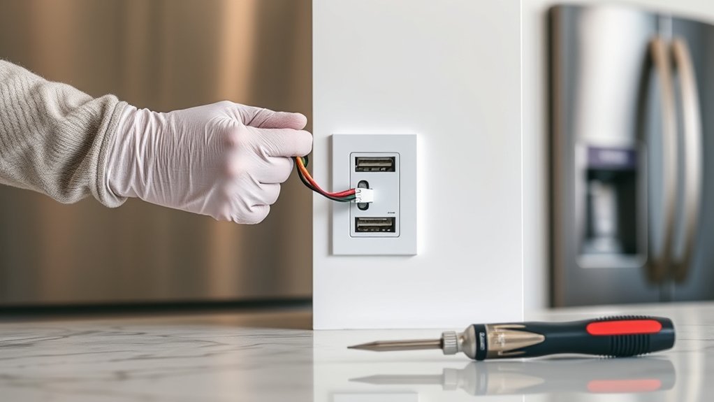
Installing a USB outlet can replace a standard receptacle with built-in USB-A or USB-C charging while keeping normal AC outlets available. The job is only straightforward when the replacement device matches the circuit, electrical box, wiring configuration, and protection required at that location. This guide assumes a typical U.S. 120-volt residential branch circuit; local electrical rules, permit requirements, and wiring methods can differ.
Quick Answer
To install a USB outlet, choose a listed receptacle that matches the circuit, box space, and required GFCI or tamper-resistant protection. Shut off the breaker, verify the circuit is de-energized with a properly rated tester, photograph the wiring, then connect line, neutral, and ground exactly as the manufacturer directs. Restore power only after the device and cover plate are secured.
Key Takeaways
- Turn off the correct breaker and verify the testing device works before relying on it.
- Check the USB outlet’s amperage rating, wiring method, dimensions, USB wattage, and installation instructions before disconnecting the old receptacle.
- A deep USB receptacle may not fit safely in a shallow or crowded electrical box.
- Do not assume a USB outlet can replace a split-fed, switched, ungrounded, aluminum-wired, or otherwise unusual receptacle.
- USB-C does not automatically mean laptop fast charging; adequate USB Power Delivery wattage is required.
- Stop and use a licensed electrician when the wiring configuration, grounding, protection requirements, or absence of voltage cannot be confirmed confidently.
At a Glance
| Time Required | About 30–60 minutes for a straightforward replacement; longer if the box or wiring needs correction. |
| Difficulty | Moderate. Appropriate only for someone comfortable identifying conventional residential receptacle wiring and safely verifying that a circuit is de-energized. |
| Tools Needed | Properly rated voltage tester, screwdriver, wire stripper/cutter if required, flashlight, manufacturer-specified torque tool when required, and a receptacle tester suitable for the circuit. |
| Cost | Varies by USB-A, USB-C, Power Delivery, amperage, GFCI features, wall plate, test equipment, and local electrician labor. |
Warning: Household branch-circuit wiring can cause severe shock, burns, fire, or death. Do not work on conductors until the circuit has been shut off and absence of voltage has been established with suitable test equipment. If you find multiple circuits, damaged conductors, aluminum wiring not approved for the new device, missing grounding, an unclear wiring arrangement, or anything that does not match the manufacturer’s instructions, stop and use a licensed electrician.
Shut Off Power to the Outlet
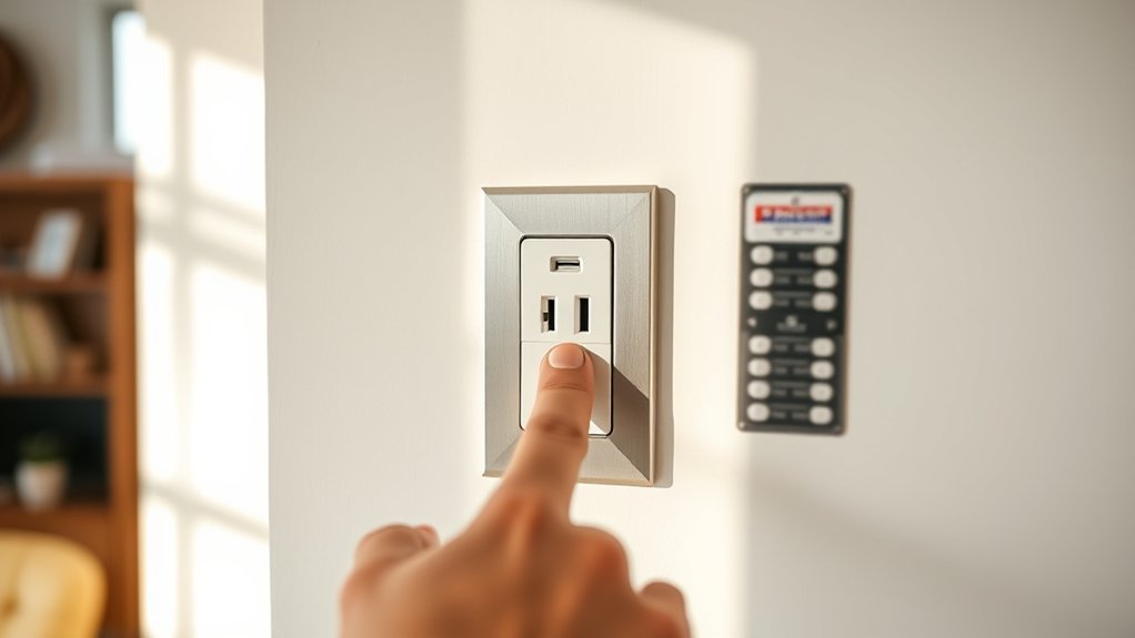
Switch off the circuit breaker that supplies the receptacle you plan to replace. Do not rely only on a handwritten panel label because circuits may have been changed or mislabeled over time.
Check the outlet before removing the cover plate. A non-contact voltage tester can be useful as an initial screening tool, but it should not be treated as infallible. Follow the tester manufacturer’s directions and verify that the tester responds correctly on a known live source before relying on a no-voltage indication. Fluke also recommends checking the tester again after the test because a failed tester can create a false sense of safety. See Fluke’s non-contact voltage detector guidance.
If you cannot confidently establish that the branch circuit is de-energized, do not continue.
Pro Tip: Test your voltage tester on a known energized source before and after checking the outlet. A tester that does not respond where voltage is known to exist should not be trusted on the circuit you intend to work on.
Gather Tools for the USB Outlet Install
Gather everything before opening the box so the circuit can remain off until installation is complete. A typical replacement may require a properly rated voltage tester, flat and Phillips screwdrivers, wire strippers, a flashlight, a receptacle tester, and any torque tool called for by the USB outlet manufacturer.
[Amazon Products Picked for You]

【10 IN 1 USB Wall Outlet Extender】- 6 AC outlet adapter (3 side, 15A/125V/1875W) with built-in 1800 Joules surge protector and 4 USB charging ports (2 USB C, total output DC 5V/3.1A), 180 degree rotating AC plug. The grounded indicator light that assures your devices are secure. WARNING: Please read the user manual before use.

3-Ports USB Electrical Outlet (1*Type C & 2*Type A) with total 5V DC, 6.0 Amp, 30W Charging Capacity

In-wall 2-port USB charging outlet with an output of 3A USB-C and 2.4A USB-A (for a total max output of 4.2A); includes 1x Type-A USB port, 1x Type-C USB port, and two 15A tamper-resistant plug outlets; does not support fast charging technologies
Essential Hand Tools
A screwdriver removes the wall plate, mounting screws, and any screw terminals used by the existing or replacement receptacle. Wire strippers are needed only when a conductor must be re-stripped to the length specified by the manufacturer. Do not guess at strip length; many devices include a strip gauge on the body or instruction sheet.
A flashlight or portable work light helps you inspect the box without restoring power to the room.
Electrical tape can be kept available, but it is not a substitute for correct termination, intact insulation, adequate box space, or proper torque. Many current manufacturer installation sheets do not require wrapping the entire receptacle in tape. If tape is used, it should not cover identification markings, USB electronics openings, or any location the manufacturer’s instructions require to remain clear.
Safety Testing Gear
Use electrical test equipment appropriate for the voltage and environment. A non-contact tester is convenient for preliminary checks, while a plug-in receptacle tester can help check the finished receptacle from the front after everything has been mounted and the cover plate installed.
Do not improvise by probing exposed energized terminals simply to see whether the installation works. If troubleshooting requires live electrical measurements, that is a strong reason for an inexperienced DIYer to use a qualified electrician.
Choose a Compatible USB Outlet
USB receptacles are not interchangeable simply because they fit a standard wall plate. Check the device label and instruction sheet before installation.
| Feature | What to Check |
|---|---|
| AC receptacle rating | Match the replacement device to the branch circuit and applicable code requirements. |
| USB type | Choose USB-A, USB-C, or a combination based on the devices you actually charge. |
| USB output | Check wattage and supported charging protocols rather than assuming all USB ports have the same output. |
| USB-C Power Delivery | Choose adequate PD wattage if you expect to charge compatible tablets or laptops. |
| Tamper resistance | Use a listed tamper-resistant receptacle where required. The CPSC also recommends tamper-resistant types when replacing household receptacles. |
| GFCI protection | Preserve or provide GFCI protection where the location requires it. |
| Conductor compatibility | Use only wire types and gauges expressly permitted by the selected device. |
| Wiring configuration | Confirm the USB receptacle supports the existing arrangement; some models cannot replace a separately fed or split receptacle. |
Modern products vary widely. For example, Leviton’s current USB outlet range includes products with different USB configurations and wattages, including USB-C Power Delivery models. Always use the rating of the exact device in your hand.
[Amazon Products Picked for You]

SMART - Built-in smart chip recognizes the individual device’s charging requirements to optimize the charge (Does not provide Power Delivery. See Leviton T5635 and T5636)

SUPERIOR CHARGING - With 60W of power on a single port, enjoy up to 2x the charging power with PD-enabled devices

In-wall 2-port USB charging outlet with an output of 3A USB-C and 2.4A USB-A (for a total max output of 4.2A); includes 1x Type-A USB port, 1x Type-C USB port, and two 15A tamper-resistant plug outlets; does not support fast charging technologies
Check Box Size, Protection, and Existing Wiring
USB receptacles contain charging electronics, so many are deeper than a basic duplex receptacle. Before committing to the replacement, make sure the existing electrical box has enough physical room and satisfies applicable box-fill requirements.
For example, one Eaton USB receptacle instruction sheet specifies a minimum 3-inch × 2-inch × 2½-inch-deep box and directs installers to comply with electrical-code box-fill requirements. Other models have different dimensions, so the manufacturer’s instructions control for the specific product.
Also check whether the existing outlet is GFCI-protected, tamper-resistant, switched, or wired as part of a special configuration. Kitchens, bathrooms, garages, outdoor locations, laundry areas, basements, and other locations may have additional protection requirements under the electrical code adopted in your jurisdiction.
Note: The current published edition of NFPA 70, National Electrical Code, is the 2026 edition, but states and local authorities adopt and amend electrical codes on different schedules. Check the requirements enforced by your authority having jurisdiction rather than assuming the newest national edition automatically governs your project.
[Amazon Products Picked for You]

𝐌𝐨𝐝𝐞𝐫𝐧 𝐃𝐞𝐬𝐢𝐠𝐧 - Screwless Wall Plate Included. USB receptacle with sleek design and glossy smooth finish, prevents fingerprint, allow for easy cleaning. Screwless Wall Plate Dimensions: 4.50”H × 2.75”L

【Save space】The Recessed Outlet can hide the plugs and sockets inside the wall, allowing the device to be closer to the wall, Flatter and more beautiful. The shell has a flat texture and can be dyed to match the color of the wall.

Our 20 Amp GFCI outlet features two USB ports (Type-A and Type-C) with a max output of 5V/4.5A, along with a 120V, 20 AMP GFCI receptacle that enhances safety by interrupting power during a ground fault. Ideal for various outdoor applications;
Remove the Old Outlet Safely
With the breaker off and the circuit verified de-energized, remove the cover plate and the receptacle mounting screws. Gently pull the receptacle forward without pulling hard on the conductors.
| Step | Action | Purpose |
|---|---|---|
| 1 | Switch off the correct breaker | Isolate the branch circuit |
| 2 | Verify test equipment and check for voltage | Reduce risk of contacting energized wiring |
| 3 | Remove the plate and mounting screws | Expose the existing wiring without disturbing it unnecessarily |
| 4 | Inspect before disconnecting | Identify nonstandard wiring or damage |
Stop before disconnecting anything if you see two different circuits, a broken tab on the old receptacle, unusual jumpers, damaged insulation, overheated terminals, missing grounding, aluminum conductors that are not approved for the replacement device, or anything you do not understand.
Some USB receptacles specifically cannot be used for separate-feed installations. A current Leviton instruction sheet, for example, warns that certain USB models cannot replace an outlet whose upper and lower receptacles are controlled by separate circuit breakers.
Check and Photograph the Existing Wiring
Before removing a single conductor, photograph the original receptacle from several clear angles. The pictures should show which conductors connect to each terminal, whether there are pigtails, and whether more than one cable enters the box.
Verify Power Is Off
Keep the breaker off throughout disassembly and wiring. Verify your tester is functioning and recheck the conductors according to the tester manufacturer’s instructions after the receptacle is pulled forward.
| Action | Purpose |
|---|---|
| Switch off breaker | Isolate the intended circuit |
| Confirm tester operation on a known live source | Make sure the tester is working |
| Check the receptacle | Screen for remaining voltage |
| Pull the device forward carefully | Expose conductors without stressing them |
| Recheck before touching conductors | Confirm conditions have not changed |
A non-contact detector is useful, but it has limitations and can produce false readings. If there is any uncertainty, use an appropriate additional verification method or stop and call a qualified electrician.
Photograph Wire Layout
Take a clear, well-lit photograph before removing the wires. In common North American residential wiring, black is often hot, white is often neutral, and bare copper or green is commonly equipment ground. However, do not rely on color alone when wiring appears altered or nonstandard.
Photograph terminal locations, pigtails, cable count, and any broken connecting tab on the original receptacle. Temporary labels can also help keep conductors organized.
If the old receptacle has a wiring configuration that the new USB receptacle’s instruction sheet does not show, stop rather than improvising a conversion.
Connect Hot, Neutral, and Ground Wires
Follow the exact wiring diagram supplied with the USB outlet. On a conventional compatible receptacle, the hot conductor normally connects to the terminal identified for line/hot, neutral to the neutral terminal, and equipment ground to the grounding terminal.
Do not automatically form every conductor into a clockwise hook. Some receptacles use side-wire screws, while others use pressure plates or screw-clamp back wiring. Use only the termination method permitted by the manufacturer.
Strip insulation to the length shown on the device or instruction sheet. No damaged insulation should be trapped in the terminal, and unnecessary bare copper should not remain exposed outside the terminal area.
Tighten terminal screws to the manufacturer’s specified torque when one is provided. For example, Eaton specifies 14 lbf-in for certain USB receptacles, but that value must not be assumed for every brand or model.
The manufacturer’s conductor restrictions also matter. Some current devices specify copper or copper-clad conductors only. If the existing wiring material or gauge is not approved for the new outlet, do not install it.
Inspect Terminals and Mount the USB Outlet
After wiring, inspect every termination before pushing the receptacle into the box. Conductors should be secure, insulation should be intact, and no loose copper strands or excessive bare conductor should be exposed.
- Compare every connection with the manufacturer’s wiring diagram and your original photographs.
- Confirm all terminal screws or clamps are tightened as specified.
- If electrical tape is used around the sides of the receptacle, use it only where appropriate and never as a substitute for a correct termination.
- Do not cover labels, marked openings, controls, or ventilation features on a device that requires them to remain clear.
- Fold the conductors carefully into the box without sharp bends, pinching, or forcing the receptacle against an overcrowded bundle.
- Mount the outlet squarely with the provided or approved mounting screws.
If the receptacle will not fit without substantial force, stop. The box may be too shallow or overcrowded for that USB model.
Reattach the Cover Plate
With the device firmly mounted, install the correct wall plate. The plate should sit flat against the wall and should not force the receptacle out of alignment.
| Checkpoint | Desired Condition |
|---|---|
| Receptacle position | Straight and firmly secured |
| Wall plate | Flush and undamaged |
| Conductors | Contained inside the box without pinching |
| USB openings | Clear and unobstructed |
Tighten wall-plate screws only enough to hold the plate securely. Excessive tightening can distort or crack some plastic plates.
Restore Power and Test the USB Outlet
After the receptacle and cover plate are fully installed, restore power at the breaker.
Do not remove the device again or touch exposed terminals while the circuit is energized merely to confirm voltage. Instead, test the finished installation from the front.
- Use a suitable plug-in receptacle tester, or test the AC receptacle with an appropriate small appliance, according to the test device’s instructions.
- If the location uses a GFCI receptacle or upstream GFCI protection, operate the applicable TEST and RESET controls according to the manufacturer’s instructions.
- Connect a known-good USB cable and a compatible phone or other portable device.
- Confirm that the device begins charging and remains connected normally.
- If testing USB-C Power Delivery, use a device and cable that support the outlet’s advertised PD profile.
Charging speed depends on the outlet’s actual rating, the USB protocol, the connected device, and the cable. There is no universal “5.1A USB outlet” specification.
For example, a current Leviton 60W dual USB-C Power Delivery receptacle can negotiate different voltage and current combinations with compatible devices. A basic 5V USB outlet may charge a phone but may not provide the USB-C PD wattage required by a laptop.
Troubleshoot USB Outlet Problems and Placement
If the finished outlet does not work, switch the breaker back off before reopening the box. Do not troubleshoot exposed wiring while energized unless you are qualified and equipped to perform that work safely.
| Symptom | Possible Cause | Safer Next Step |
|---|---|---|
| AC outlet and USB ports both dead | Breaker/GFCI off, incorrect connection, or circuit problem | Check breaker and GFCI status; de-energize before inspecting wiring |
| AC works but USB does not | Cable/device incompatibility or defective USB electronics | Try a known-good compatible cable and device; check the outlet specifications |
| Slow charging | Low outlet wattage, unsupported charging protocol, cable limitation, or shared output | Compare the device, cable, and outlet charging ratings |
| Laptop will not charge | Outlet lacks sufficient USB-C PD output | Check the laptop’s required USB-C PD wattage and the outlet’s rated output |
| Outlet or wall plate becomes unusually hot | Loose connection, excessive heating, damaged device, or other fault | Stop using it, switch off the breaker, and have the installation inspected |
| Breaker or GFCI trips repeatedly | Wiring fault, damaged device, or circuit issue | Stop resetting repeatedly and have the cause diagnosed |
Good installation locations include bedrooms, home offices, and other dry areas where built-in charging is useful. Kitchens and other protected locations can also use USB receptacles when the installation preserves all required GFCI and other protection.
Frequently Asked Questions
Do USB Ports Work in Safe Mode?
Computer USB ports usually retain at least some basic functions in an operating system’s Safe Mode, although driver-dependent devices may behave differently. An in-wall USB charging outlet is different: it does not depend on Windows, Android, or another operating system and normally continues supplying charging power whenever its branch circuit is energized and the outlet is operating correctly.
How Do You Change USB Port Power Settings?
Power-management settings in Device Manager or an operating system apply to computer USB ports, not a built-in wall charger. An in-wall USB outlet manages charging internally according to its design and supported charging protocol. To obtain more charging power, the receptacle itself must support the required USB standard and wattage.
How Do You Add a USB Outlet?
Choose a listed USB receptacle compatible with the circuit, box, wiring configuration, and required GFCI or tamper-resistant protection. De-energize and verify the circuit, document the existing wiring, connect the replacement exactly as its manufacturer instructs, mount the device and wall plate, restore power, and test it from the front.
How Do I Enable My USB Port?
A USB port built into a wall receptacle normally has no software enable/disable setting. It should operate when the branch circuit is energized and the receptacle is functioning correctly. If it does not charge, check the cable, device compatibility, GFCI or breaker status, and the outlet’s rated charging output.
Does a USB Outlet Need GFCI Protection?
It depends on where the receptacle is installed and the electrical code enforced locally. Locations such as kitchens, bathrooms, garages, outdoor areas and other specified spaces commonly require GFCI protection. Protection may be built into the USB receptacle or supplied upstream when the installation method and local code allow it.
Can a USB-C Wall Outlet Charge a Laptop?
Some can, but USB-C connector shape alone does not guarantee laptop charging. The outlet must support USB Power Delivery at enough wattage for the laptop, and the USB-C cable must also support the required power. Check the computer’s charging requirement and the receptacle’s published PD output before relying on it.
Conclusion
A USB outlet installation can be a useful upgrade when the replacement receptacle matches the existing circuit, wiring method, electrical box, and required protection. The safest approach is to verify the circuit is de-energized, photograph the original wiring, and follow the exact strip length, terminal method, conductor restrictions, and torque values supplied by the outlet manufacturer.
Do not assume every USB receptacle provides the same charging power. Basic USB outlets and modern USB-C Power Delivery models can have very different capabilities. After installation, test the completed receptacle from the front rather than exposing energized terminals. Any unexplained heat, repeated tripping, damaged wiring, nonstandard configuration, or uncertainty about grounding or code requirements should be handled by a qualified electrician.
Sources
- Leviton USB Product Support — current USB receptacle types, wattages, and manufacturer installation resources.
- Leviton 60W USB-C Power Delivery Receptacle Instructions — wiring precautions, charging profiles, device limitations, and installation guidance.
- Eaton USB Receptacle Installation Instructions — box size, conductor, terminal, grounding, and torque requirements for the covered models.
- Fluke Non-Contact Voltage Detector Guidance — tester verification, limitations, and safe-use practices.
- U.S. Consumer Product Safety Commission — recommendation to use tamper-resistant receptacles when replacing household receptacles.
- NFPA 70, National Electrical Code — current national electrical-code reference; local adoption and amendments determine enforceable requirements.
