
Drone mapping often fails at the coordinate system level, not the sensor level. WGS84, UTM, and State Plane can each be valid, yet a mismatch in datum or projection can shift ground control points by meters or more. Those offsets can distort orthomosaics, elevation models, and measurements in ways that are not immediately obvious. The real issue is usually hidden in the export settings, where one small choice changes everything.
Why Drone Maps Misalign
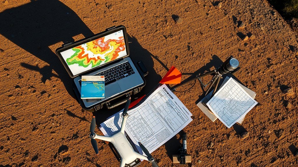
Drone maps often misalign when the ground control points and imagery are referenced to different coordinate systems or datums, such as WGS84 versus State Plane or NAD27 versus NAD83. A Coordinate System mismatch shifts control points relative to the image block, producing warped outputs and misleading error messages.
When operators choose the wrong reference framework during processing, GCPs may be placed in the wrong location, triggering warnings that points lie far from image positions. Datum differences can introduce offsets of 10 to 100 meters, enough to displace roads, parcels, and infrastructure.
Import problems also contribute: incorrect field mapping, malformed files, or unsupported formatting can prevent validation and preserve error. Clear communication with surveyors is essential; EPSG confusion, such as substituting EPSG:3044 for EPSG:25832, can alter Easting values and corrupt alignment.
Import errors and EPSG mix-ups can quietly skew Easting values and corrupt alignment.
Accurate mapping depends on precise reference control, not guesswork, so spatial truth remains accessible.
WGS84, UTM, and GCPs: What Must Match
Successful drone mapping depends on coordinate consistency: GNSS positions are typically recorded in WGS84, while ground control points must be expressed in the same project reference frame, such as UTM or State Plane, for the dataset to align correctly.
Any mismatch between WGS84 and the project grid can shift imagery and distort measurements.
- Match the datum: confirm whether GCPs are referenced to WGS84, NAD83, or another datum.
- Match the projection: verify imagery and GCPs use the same UTM zone; zone errors create systematic offset.
- Verify GCPs: survey-grade confirmation reduces hidden coordinate mistakes before processing.
- Watch software warnings: “far from expected image location” usually indicates incompatible coordinate definitions.
Precise alignment gives operators freedom from avoidable rework, supports defensible outputs, and keeps the mapping workflow analytically clean.
How State Plane Coordinates Work
The State Plane Coordinate System partitions the United States into narrow zones to maximize local mapping precision, with zone limits often aligned to county boundaries.
Each zone applies either Transverse Mercator or Lambert Conformal projection around a central meridian, using Cartesian eastings and northings measured in feet or meters.
Accurate use depends on the correct datum, since NAD83 and older NAD27 references can introduce substantial coordinate shifts.
Zone-Based Precision
State Plane Coordinate Systems divide each state into multiple zones, often aligned with county boundaries to preserve surveying accuracy over relatively small areas.
State Plane achieves zone-based precision by limiting distortion, letting local data remain faithful to the ground.
- Zones are selected for regional fit, not broad national coverage.
- North-south states commonly use Transverse Mercator.
- East-west states commonly use Lambert Conformal.
- Coordinates are expressed in feet or meters, with eastings on X and northings on Y.
This structure supports disciplined surveying and mapping, reducing positional drift that can undermine ground control points.
Modern NAD83-based zones differ from older NAD27 references, so legacy layers may shift by 10-100 meters if the datum is mismatched.
Correct zone selection is thus essential for spatial autonomy.
Projection And Origin
Projection in the State Plane Coordinate System is defined by a zone-specific map projection and a fixed origin framework that keeps local measurements tightly aligned with the ground.
Each zone uses a projection chosen for geometry: Transverse Mercator for tall north-south states, Lambert Conformal for wide east-west states. A central meridian passes through the zone center, and coordinates are cast into a Cartesian grid with eastings on the X-axis and northings on the Y-axis.
This structure gives local surveys and drone control points a disciplined reference, reducing distortion and preserving spatial freedom from arbitrary scale drift.
State boundaries may contain one to six zones, often aligned to counties, so the projection and origin must be matched exactly for accurate GIS integration.
Datum Shifts Matter
Datum changes can shift a dataset by 10 to 100 meters when historical maps use NAD27 and modern GPS or GIS workflows assume NAD83. In State Plane, datum shifts are not noise; they are a structural mismatch that can displace control, boundaries, and drone imagery.
- SPCS uses zone-specific projections, often Transverse Mercator or Lambert Conformal, to preserve local accuracy.
- Coordinates are expressed as eastings and northings in feet or meters, forming a Cartesian grid.
- When GPS points and SPCS layers use different datums, alignment errors emerge immediately.
- Selecting the correct realization, such as NAD83 Washington State Plane South Feet 2927, keeps GCPs authoritative and mapping liberated from inherited spatial distortion.
Why Datums Shift Your GCPs
When Ground Control Points are entered in one datum while the project imagery is referenced to another, their positions can shift markedly because each datum defines a different Earth-centered frame of reference.
Datums are not interchangeable labels; they establish distinct mathematical surfaces and control how latitude, longitude, and elevation are interpreted. A switch from NAD27 to NAD83, for example, can move GCPs by 10 to 100 meters, enough to corrupt feature placement and weaken spatial analysis.
Historical maps often preserve obsolete datums, so legacy coordinates may appear valid while actually encoding a displaced reference frame.
Accurate mapping thus depends on identifying the original datum, selecting the project datum deliberately, and applying the correct transformation before analysis.
Without that discipline, the data cannot be trusted to align with the intended coordinate system, and the resulting map inherits avoidable positional error.
How to Match GCPs and Imagery
Matching Ground Control Points to drone imagery requires placing both datasets in the same coordinate system before any alignment is evaluated. A GCP set collected in State Plane must be transformed, when needed, to the imagery’s Coordinate reference, often WGS84 or UTM, so positional comparisons are meaningful.
GIS software such as ArcMap can reproject points into the target Coordinate framework, reducing systematic offsets and freeing the map from hidden mismatch.
- Confirm the imagery Coordinate system first.
- Reproject GCPs with the correct NAD83 or EPSG code.
- Check X/Y import fields for formatting errors.
- Verify the surveyor’s stated Coordinate system before processing.
For Washington, EPSG:2927 identifies State Plane South and prevents category errors that distort placement.
Careful Coordinate matching preserves analytical integrity, improves libertarian access to truthful spatial data, and supports map outputs that reflect ground conditions rather than projection artifacts.
What GPS and GIS Can Export
Once GPS and GIS datasets are aligned to the same coordinate framework, their export options determine how readily they can be reused in mapping workflows. GPS receivers commonly output positions in WGS84, UTM, or SPCS, giving analysts direct access to geographic and Plane coordinates for field capture, surveying, and drone control.
GIS platforms extend this capability by exporting maps, features, and attribute tables as Shapefile, GeoJSON, or KML, formats that move cleanly across software ecosystems. Coordinate transformation tools preserve interoperability by converting among reference systems without changing the underlying spatial intent.
Exported files may also carry metadata, including CRS and datum definitions, which support reproducible analysis and reduce ambiguity. When GPS observations are integrated into GIS, real-time location data can strengthen alignment with existing layers, enabling more independent and precise mapping practices.
How to Fix Coordinate System Errors
Coordinate system errors are typically resolved by matching the project datum and projection to the drone imagery before any processing begins.
Ground control points should be reprojected into the same coordinate system as the imagery, with zone and unit settings verified against the survey data.
If discrepancies persist, offset corrections and coordinate formatting checks can be used to isolate import or alignment faults.
Match Project Datums
Project datums must align before any drone mapping adjustment can be trusted, because even small coordinate system mismatches between Ground Control Points (GCPs) and imagery can produce visible misalignment and biased outputs.
The coordinate system’s datum defines how positions are interpreted, so consistency across layers is nonnegotiable for accurate, emancipated mapping.
- Confirm GCPs and imagery share one datum.
- Verify EPSG codes with surveyors to prevent silent errors.
- Use ArcMap or equivalent software to reproject into the project datum.
- Validate import field mappings so X/Y values match the required format.
Selecting the correct NAD83 Washington State Plane South option avoids displacement that can corrupt control.
Precision here protects analytical freedom and keeps mapping results spatially coherent.
Reproject GCP Coordinates
To correct coordinate system errors, GCPs must be reprojected into the same spatial reference used by the imagery, often converting between systems such as NAD83 and WGS84 or another project-specific datum. The process to reproject gcp coordinates should be executed with GIS software, and ArcMap can apply AddXY, then export corrected values to CSV. Selecting the proper NAD 83 variant, such as Washington State Plane South Feet 2927, preserves positional integrity. When EPSG:3044 produces offsets, Easting may require subtracting 32,000,000 to restore alignment.
| Action | Purpose |
|---|---|
| Reproject GCPs | Match imagery reference |
| Apply AddXY | Capture corrected coordinates |
| Export CSV | Enable downstream use |
| Adjust offsets | Restore spatial coherence |
| Surveyor check | Confirm precise placement |
Verify Zone And Units
A common source of coordinate system errors is a mismatch in zone or unit definitions between GCPs and imagery, which can produce large spatial offsets even when the values appear valid. To verify zone and units, the operator should compare the project CRS, GCP metadata, and image georeference before processing.
- Confirm both datasets use the same coordinate system.
- In State Plane, verify the exact zone; a wrong zone displaces points.
- Ascertain feet or meters are consistent across all layers.
- Use ArcMap or similar tools to convert GCPs, then validate warnings that place points far from image positions.
This disciplined check preserves spatial truth and prevents avoidable misalignment in liberated, accurate mapping workflows.
Frequently Asked Questions
What Is the Difference Between UTM and WGS84 Coordinates?
UTM coordinates differ from WGS84 coordinates in both form and purpose.
WGS84 expresses position as latitude and longitude on a global ellipsoid, supporting GPS and broad navigation.
UTM converts that same Earth position into zone-specific eastings and northings in meters, improving Geospatial Accuracy for local analysis.
The result is a projected metric system that reduces distortion within each zone, while WGS84 remains a geographic reference free from zone boundaries.
How Do I Convert UTM Coordinates to WGS84 Coordinates?
UTM coordinates convert to WGS84 through disciplined Conversion Techniques, as if opening a sealed cartographic gate.
A GIS tool or online transformer is used, with the correct UTM zone, hemisphere, and datum selected first.
Datum shifts, such as NAD27 to NAD83, must be resolved to preserve positional freedom and accuracy.
The output becomes latitude and longitude in WGS84, ready for analytical use and interoperable mapping workflows.
What Are the Differences Between UTM and State Plane Coordinates?
UTM and State Plane differ in scope, projection design, and Coordinate Accuracy.
UTM divides Earth into 60 meter-based zones using a Transverse Mercator projection, optimizing consistency across broad regions.
State Plane uses state-specific zones, often smaller and more precise, with Transverse Mercator or Lambert Conformal projections.
UTM suits general mapping; State Plane supports higher local precision, reducing distortion and freeing spatial analysis from unnecessary regional compromise.
What Are the Four Types of Coordinate Systems?
A survey team once found a bridge shifted on screen, then realized the project mixed coordinate systems.
The four types are geographic, projected, local, and geocentric. Geographic systems use latitude and longitude on Geodetic Datums; projected systems flatten Earth onto a plane; local systems define site-specific grids; geocentric systems reference Earth’s center.
Each serves different analytical demands, enabling precise spatial control and reducing dependence on incompatible mapping frameworks.
Conclusion
Accurate drone mapping depends on a single, consistent coordinate framework across imagery, GCPs, and GIS exports. WGS84, UTM, and State Plane are not interchangeable, and datum shifts can displace control points by tens of meters. A common objection is that small offsets are acceptable, but in survey and infrastructure work they can invalidate measurements and decisions. Reliable outputs require matching projections, verifying datums, and correcting coordinate system errors before analysis or delivery.