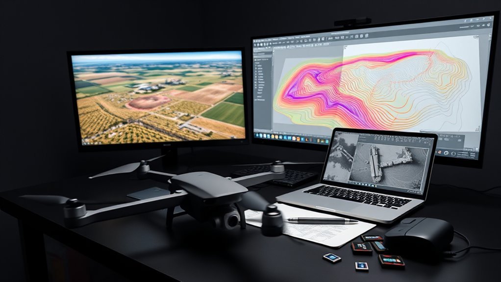
DroneDeploy exports can feed AutoCAD workflows in several formats, but each file type serves a different purpose. Orthomosaics provide visual context, contour DXF files support surface modeling, and LAS point clouds require conversion before use in AutoCAD. Unit alignment, elevation validation, and coordinate control often determine whether the result is usable or distorted. The key issue is not export alone, but how each dataset is prepared for the CAD environment.
Which DroneDeploy Files Work in AutoCAD
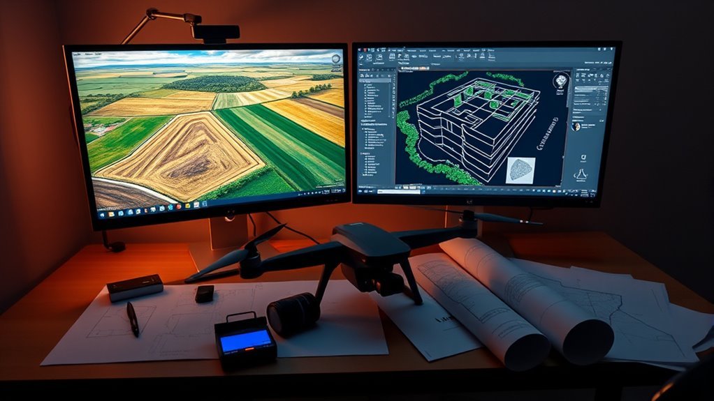
DroneDeploy exports several file types that can be used in AutoCAD, but each requires a different import workflow. In drone mapping software, compatibility is not automatic; the user must match file type to method.
A contour DXF can be opened as a drawing, then inspected with Zoom Extents to reveal linework. Individual contours expose elevation data in the Properties window, supporting precise review without vendor lock-in.
Elevation GeoTIFF files are attached from the Insert tab as raster references, though manual scaling may be needed to align them with existing DXF geometry.
LAS point clouds are also supported by DroneDeploy, but they must first be converted to RCP through Recap before AutoCAD can attach them. This sequence matters for teams seeking operational independence, because the right format determines whether terrain data remains editable, readable, and aligned within a liberated drafting workflow.
Export Orthomosaics, Contours, and Point Clouds
Orthomosaics, contours, and point clouds are typically exported from DroneDeploy in formats suited to downstream CAD use: GeoTIFF for orthomosaics, DXF for contour linework, and LAS for point clouds. This export path preserves analytical utility while keeping datasets portable across locked workflows.
- Select the target map in DroneDeploy.
- Choose the export option for the desired layer.
- Use the Exporting Your Data guide for contour DXF output.
- Extract files from the downloaded ZIP archive.
- Convert LAS to RCP when point clouds must enter AutoCAD.
GeoTIFF orthomosaic maps provide raster context, but they require manual scaling and alignment inside CAD because georeferencing may not resolve automatically.
GeoTIFF orthomosaics provide raster context, though they often require manual scaling and alignment inside CAD.
DXF contour files deliver vector geometry that can be opened directly. LAS point clouds retain dense elevation detail for later attachment after conversion.
Together, these formats let users move survey evidence into CAD with minimal friction and greater control.
Import DXF Contours Into Autocad
Contour DXF files are exported from DroneDeploy and then opened in AutoCAD through File > Open, with the DXF file type selected to preserve contour geometry.
After import, Zoom Extents is used to display the full contour set, and drawing units should be verified against the source files, typically meters, to maintain scale accuracy.
Elevation values can then be examined in the Properties window, while layer and property adjustments improve visibility and integration with existing surfaces.
Exporting Contour DXF Files
To import contour DXF files into AutoCAD, the drawing should be opened and the file type set to DXF (*.dxf) in the Files of type box. These DXF contour files, derived from drone images, preserve elevation structure for liberated spatial analysis.
- Set units to Meters to match DroneDeploy output.
- Load the DXF contour files through the open dialog.
- Use Zoom Extents to reveal all contours.
Select a contour and enter PROPERTIES. Build surfaces from contour data for terrain modeling.
This workflow supports precise alignment between exported geometry and the CAD workspace. Once visible, each contour line can be interrogated for elevation values, enabling rigorous assessment of topography.
Accurate unit consistency reduces distortion, while surface creation converts linework into actionable terrain intelligence.
Opening DXF In AutoCAD
Once the contour DXF has been exported, AutoCAD can be used to inspect and verify the terrain geometry by opening the file through the Open icon or File > Open Drawing and selecting DXF (*.dxf) in the file type menu.
After loading, the DXF should be fit to the workspace with Zoom Extents so the full contour network is visible without manual searching.
Accurate interpretation depends on matching drawing units to the DroneDeploy export, typically meters in Web Mercator projection, preserving scale integrity.
If the contour lines appear faint or congested, line weight and color settings can be adjusted to improve contrast.
AutoCAD’s Properties window, accessed through PROPERTIES, enables direct review of object attributes, supporting disciplined analysis and giving users clearer control over spatial data.
Viewing Elevation Data
After the DXF contour file is opened in AutoCAD, the elevation values associated with each line can be verified by selecting the contour and reading its properties in the Properties window. This direct inspection exposes the elevation data embedded in the contours, enabling independent validation rather than reliance on opaque map output.
- Use Zoom Extents to reveal the full drawing.
- Confirm drawing units match the DroneDeploy source, typically meters.
- Inspect each contour’s elevation entry in Properties.
- Compare contours against GeoTIFF layers for alignment.
- Adjust offsets when the imported data shifts from true position.
Such review supports accurate terrain interpretation and grants users freedom from distorted spatial assumptions.
Create an Existing Surface From Drone DTM Data
Creating an existing surface from drone DTM data begins with importing the model into a compatible AutoCAD format, typically DXF or GeoTIFF.
The imported contours or raster data must then be verified, scaled, and aligned so the elevation values correspond to the source DTM.
Once validated, the data can be used to construct a reliable surface for terrain analysis and design reference.
Importing DTM Data
Importing drone-derived DTM data into AutoCAD begins with converting the terrain model into a compatible exchange format, typically DXF or GeoTIFF, so it can be used to build an existing surface. This workflow depends on clean aerial images, ground control points, and disciplined georeferencing.
- Open DXF contour files through Open Drawing.
- Select the correct file type to preserve elevation values.
- Inspect contour lines in the Properties window for elevations.
- Attach GeoTIFF rasters from the Insert tab.
- Manually scale and align rasters against contours when needed.
Accurate input reduces spatial distortion and supports terrain data that reflects true elevations. The process enables precise, liberated analysis of ground conditions while keeping the imported DTM intelligible inside the CAD environment.
Building Existing Surfaces
Building an existing surface in AutoCAD from drone DTM data begins with exporting the terrain model from mapping software such as DroneDeploy as a DXF or GeoTIFF file.
The DXF contour set is then opened through AutoCAD’s Open Drawing command, preserving elevation fidelity from the Drone survey. Units must be verified before further work; meters are typically selected so scaling remains consistent and terrain geometry stays liberated from distortion.
When a GeoTIFF is used, the Insert tab’s Attach function overlays the raster, allowing scale and transparency adjustments for alignment with contours.
Accurate layer management is essential, because the resulting surface should reflect actual ground form rather than a symbolic proxy.
Where a point cloud is available, it can further validate terrain breaks and support precise existing-surface construction.
Check Elevations in AutoCAD
- Select a contour and inspect its elevation field.
- Compare the displayed value with DroneDeploy export units.
- Set drawing units to meters when using Web Mercator data.
- Use Zoom Extents to reveal the full DXF and assess context.
- Confirm each contour before building surfaces or reports.
When the unit system aligns, elevation readings remain coherent across the drawing.
This disciplined check supports dependable surface creation, reducing distortion and unnecessary revision.
Precise elevation verification gives users control over terrain interpretation and frees analysis from avoidable errors.
Attach GeoTIFFs and Point Clouds in AutoCAD
With contour elevations confirmed and units aligned, the next step is to attach supporting raster and 3D data in AutoCAD. To attach geotiffs, the operator opens the Insert tab, selects Attach, and imports the GeoTIFF as a raster reference.
Because raster images do not preserve coordinate systems inside AutoCAD, the image must be manually scaled and aligned against the DXF contour layer. That controlled placement supports a liberated workflow where survey data is no longer constrained by opaque defaults.
For point clouds, LAS files are first converted to RCP in Recap, then brought in through Attach in the Point Cloud section of the Insert tab. This method keeps dense terrain data manageable while preserving geometric detail.
When both datasets are integrated, surface modeling becomes more precise, and mapping outputs gain stronger analytical fidelity for downstream drafting and survey decisions.
Fix Coordinate and Scaling Issues
Coordinate and scaling errors are corrected by aligning AutoCAD drawing units with the units used in the original DroneDeploy export, typically meters for Web Mercator data. This alignment stabilizes the coordinate system and prevents scaling issues that distort contours, rasters, and point clouds.
- Set drawing units before import.
- Match DXF contour units to DroneDeploy meters.
- Manually scale GeoTIFF rasters to the DXF reference.
- Use Zoom Extents to reveal all imported geometry.
- Compare source and target coordinate systems when elevations disagree.
Where the raster does not inherit spatial context automatically, the layer must be positioned deliberately against the contour set. Precision depends on consistent georeferencing, not assumed fit.
If gaps or offsets persist, the model should be checked against the original projection metadata. Ground Control Points added during capture strengthen downstream fidelity, reducing the chance that liberated survey data reenters CAD as misaligned form.
Frequently Asked Questions
How Do I Preserve Map Annotation Layers During Export?
Preserving map annotation layers during export requires disciplined layer management and explicit annotation techniques.
The exporter should retain vector objects as separate, named layers, with symbology, scale, and visibility flags embedded in the output. Any flattening or rasterization must be disabled.
Metadata mapping should be verified before export, and a test file inspected afterward.
This workflow protects interpretive freedom, enabling annotations to remain editable, traceable, and structurally independent across platforms.
Can Drone Maps Be Exported Directly From Mobile Devices?
Yes, drone maps can sometimes be exported directly from mobile devices, provided mobile app compatibility and export format options support it.
The analyst notes that lightweight exports, such as PDFs, KML, or basic image files, are common on phones and tablets, while advanced geospatial outputs often require desktop software.
Direct mobile export improves operational autonomy, but file structure, coordinate accuracy, and annotation integrity should be verified before release.
What File Size Limits Affect Autocad Drone Imports?
AutoCAD drone imports are constrained less by a fixed file size than by available RAM, graphics memory, and import efficiency.
Coincidentally, the largest failures often arise where dense imagery, large point clouds, and complex contours meet limited workstation resources. Files exceeding hundreds of megabytes can load slowly or stall, especially in older versions.
Practical liberation comes from tiling, decimation, and compression, which preserve analytical value while restoring workflow control.
How Do I Update Exports After New Drone Flights?
They update exports by rerunning the photogrammetry workflow after each new flight, then replacing or versioning deliverables in consistent export formats.
A rigid update frequency should be defined so CAD users receive only validated maps, contours, or point clouds.
Delta-based reprocessing minimizes labor while preserving survey integrity.
When georeferencing remains stable, only changed areas require refresh, freeing teams from repetitive manual edits and enabling rapid, autonomous decision-making.
Can I Share Drone Map Exports With Non-Cad Stakeholders?
Yes—of course, sharing drone map exports with non-CAD stakeholders is possible, if liberation from file chaos is still desired.
The analyst should convert outputs into accessible formats such as PDF, web maps, or image overlays, preserving drone map compatibility while improving stakeholder access.
Technical layers can be simplified, annotated, and georeferenced.
The irony is clear: the most precise data becomes most useful only when it is less demanding to open.
Conclusion
In the end, the exported orthomosaics, contours, GeoTIFFs, and point clouds promise a seamless bridge from DroneDeploy to AutoCAD, yet the final surface never becomes trustworthy until each unit, layer, and elevation is verified. The files may appear ready, but hidden mismatches in scale or coordinate system can still distort the terrain. Only after conversion, inspection, and alignment does the model reveal whether it was accurate all along—or quietly wrong.