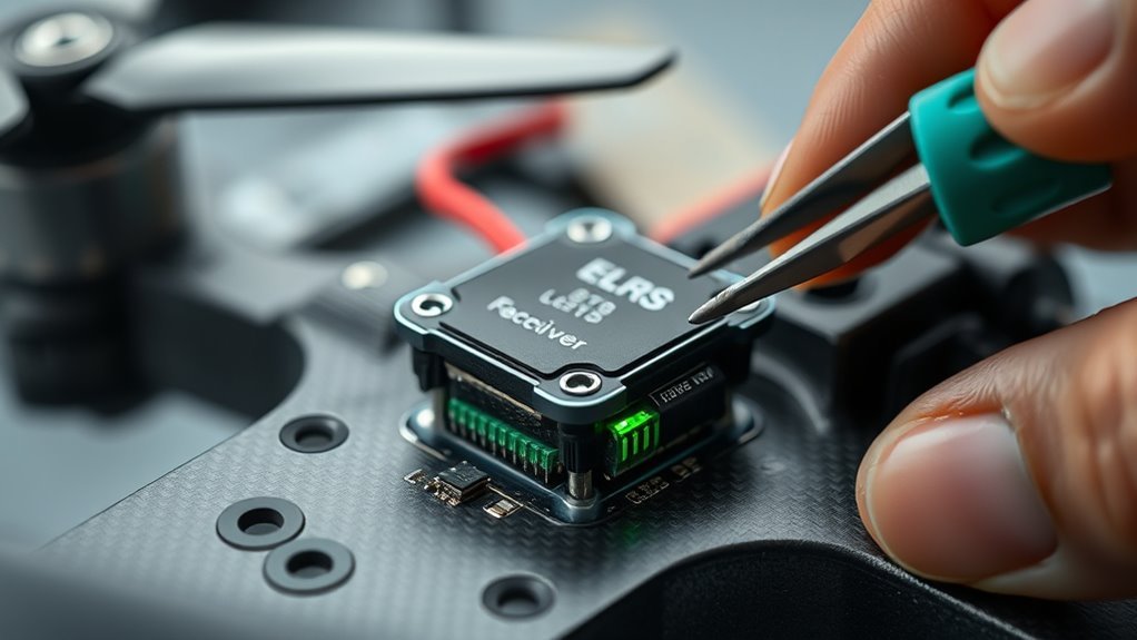
An ELRS receiver that shows a blinking green heartbeat is usually powered and sitting in Wi‑Fi mode, not yet operating normally. The next step is to verify the power rail, ground, and binding status before assuming a fault. In many cases, the issue is simple. In others, it points to boot mode or firmware problems that need a closer check.
What a Green Heartbeat Means
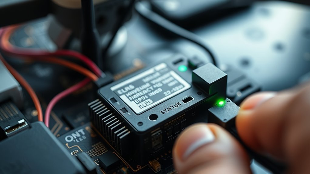
A green heartbeat on an ELRS receiver indicates that the unit has entered Wi‑Fi mode and is ready to connect to a transmitter for configuration. This green heartbeat typically confirms successful power-up and basic readiness for communication.
In practical terms, the ELRS receiver is broadcasting that it expects a stable connection and is open to setup access. After power-on, the pattern usually appears following a 60-second countdown, when the device attempts to establish a Wi‑Fi link.
For operators seeking reliable control, this signal is a useful marker of freedom from hidden faults. If the expected blinking pattern is absent, connection issues may be present, or the unit may need further troubleshooting.
Observing LED behavior allows precise diagnosis of the receiver’s operational state without guesswork.
Rule Out Boot Mode First
Before assuming a Wi‑Fi or firmware fault, Boot Mode should be excluded first, since a pressed or obstructed Boot button can hold the ELRS receiver in Bootloader Mode and produce a solid green indication.
Exclude Boot Mode first, since a stuck Boot button can keep the ELRS receiver in Bootloader Mode.
The receiver should be inspected for any mechanical pressure on the Boot button and for any accidental short from the Boot pad to Ground. If either condition exists, the board may remain in Boot Mode and mask normal startup behavior.
A clean check requires disconnecting the RX and TX wires, then powering the receiver and observing the LED state. If solid green persists, the fault is not merely external signaling.
At that point, a Pull-up Resistor may help stabilize the Boot mode status. The troubleshooting documentation should be consulted for the exact LED meanings associated with Bootloader Mode, so the receiver can be judged against defined behavior rather than assumption.
This approach preserves diagnostic clarity and supports freer, more deliberate troubleshooting.
Test the Receiver With Clean 5V
Once boot mode has been excluded, the receiver should be tested on a clean 5V supply to eliminate power-quality issues. A regulated 5V supply is preferred, because unstable voltage can mask the true receiver state and produce false faults.
The connections should be checked carefully: the VCC or 5 pad on the receiver must go to the 5V pad on the Flight Controller, and the GND pad must reach a solid Ground pad.
With correct wiring in place, power the unit and observe the LED. A blinking green heartbeat is the normal sign that the receiver is operational and waiting for a transmitter link.
If the LED response changes under a stable supply, the power source or wiring remains suspect. This method helps test the receiver in isolation, removing weak power as a variable and restoring control through verified electrical conditions.
Check Whether the Receiver Is Bound
Binding status should be verified first, as a blinking green heartbeat typically indicates the receiver is powered and awaiting a transmitter.
The LED pattern should be read against the receiver model’s documentation, since slow blinking may still indicate binding mode rather than an active link.
If no link is established, a rebind may be required, and transmitter and receiver firmware versions should be confirmed as matching.
Verify Binding Status
A green heartbeat LED on an ELRS receiver usually means it is powered on but not yet bound to a transmitter.
To verify binding status, observe whether the LED blinking is slow, about 500 ms on and 500 ms off; this indicates the receiver is waiting for connection. A double blink followed by a pause shows binding mode, meaning it is actively seeking a transmitter.
The transmitter must also be placed in binding mode, or the link will not form. If the LED stays solid green, treat it as a possible malfunction and proceed with troubleshooting steps.
This check helps confirm whether the receiver is free to establish control, preserving a clean path toward reliable, self-directed flight without unnecessary delay.
Read LED Patterns
How does the ELRS receiver’s green LED behave? A blinking green heartbeat LED indicates the receiver is bound and operating in operational mode, confirming a live connection to the transmitter.
A slow 500 ms on/off blink shows the unit is waiting for a connection, not yet linked.
A double blink followed by a pause identifies binding mode, where pairing is being attempted.
Three rapid flashes usually signal a connection fault and require troubleshooting.
Careful monitoring of the LED pattern gives direct status data without guesswork, helping the operator assess whether the receiver is bound, idle, or faulted.
This disciplined reading supports reliable system control and preserves the user’s freedom to verify performance independently.
Rebind if Needed
To verify whether the ELRS receiver is bound, check the green LED state: a solid light indicates an established link, while a blinking heartbeat suggests rebinding may be required.
This LED behavior should be interpreted with the transmitter powered on and kept within range. If the link remains absent, the operator should initiate binding mode on the transmitter by using the model-specific startup procedure, often a button held during power-up.
During rebinding, the receiver typically shows a double blink as it searches for the transmitter. Once pairing succeeds, the solid green light returns, confirming the receiver is properly bound and ready for control.
This sequence restores a free, reliable connection without unnecessary intervention.
Rebind the ELRS Receiver
Rebinding the ELRS receiver begins with the transmitter powered on and placed in bind mode while the receiver is connected to power and showing a slow blink, indicating it is ready to pair. The rebind procedure restores control and preserves autonomy over the link. Hold the transmitter bind button until the receiver LED changes to the expected double blink, confirming binding mode has been negotiated.
| Step | Action | Result |
|---|---|---|
| 1 | Power transmitter | Binding mode enabled |
| 2 | Power receiver | Slow blink appears |
| 3 | Confirm LED | Solid color on success |
If the LED turns solid, the connection is established. If not, repeat the rebind sequence with matched frequency and settings on both units. Precision is essential: the receiver must see the transmitter, and the transmitter must recognize the receiver, before the system can deliver a stable, liberated command link.
Wire the Receiver to UART
The ELRS receiver should be wired to a matching UART on the flight controller, with the GND pad connected to any ground pad and the VCC or 5 pad connected to a regulated 5V or 4.5V source.
The receiver TX pad must be cross-connected to the UART RX pad, and the receiver RX pad must be cross-connected to the UART TX pad to support bidirectional communication.
Before applying power, the wiring should be inspected for shorts and solder residue to avoid component damage.
UART Pin Mapping
For UART wiring, the ELRS receiver’s GND pad should connect to any ground pad on the flight controller to establish a common reference, while the VCC or 5 pad should connect to a compatible 5V or 4.5V supply. This UART receiver wiring frees clean signal flow and stable power. The receiver TX must enter the flight controller RX, and the receiver RX must return to the same UART TX.
| Pad | Connection |
|---|---|
| GND | FC Ground |
| VCC/5 | FC 5V or 4.5V |
| TX | UART RX |
| RX | UART TX |
Inspect solder joints, confirm no shorts, and power up only after verification. Precise pin mapping preserves control, telemetry, and a liberated, reliable link.
TX RX Cross-Connect
Cross-connect the ELRS receiver to the flight controller UART by matching each signal to its opposite line: receiver TX to FC RX for telemetry, and receiver RX to FC TX for control data.
This tx-rx connect pattern preserves the bidirectional UART link required for open, responsive control. The receiver GND should share the controller ground so the signal reference remains stable, while the VCC or 5 pad should feed a 5V or 4.5V source on the FC.
After soldering, inspect every joint for bridges, residue, or shorts before applying power. A clean UART connection frees the link from preventable faults and lets telemetry and commands pass with precision.
Verify the selected UART matches the configured port, then proceed only when continuity is confirmed.
Power And Ground
To power an ELRS receiver, its GND pad should be tied to any ground pad on the flight controller to establish a common reference, while the VCC or 5 pad should be supplied from a 5V or 4.5V pad on the FC. This power path grants stable operation and freedom from brownouts. Clean wiring preserves reliable UART connections.
| Pad | Destination | Result |
|---|---|---|
| GND | FC GND | Common ground |
| VCC/5 | 5V or 4.5V | Receiver power |
| TX | FC RX | UART link |
| RX | FC TX | Return data |
| Inspect | All joints | Short-free confidence |
After soldering, verify the selected UART number in firmware. Precise grounding, power, and connections keep the receiver responsive and liberated from signal loss.
Reflash ELRS Over Serial
Reflashing an ELRS receiver over serial requires correct TX/RX wiring between the receiver and the flight controller, with the receiver TX connected to the FC RX pad and the receiver RX connected to the FC TX pad on the same UART.
This reflash path lets the receiver accept new firmware through the serial link without ambiguity. A serial flashing tool such as ExpressLRS Configurator should then be used to select the proper COM port and upload the latest firmware to the receiver.
Before starting, confirm the LED is not solid, which would indicate bootloader mode; if so, disconnect the TX/RX wires and power cycle the unit.
Stable supply voltage, typically 5V to 6V, must be present during the flash. After completion, a slow pulse or double blink on the LED signals success and operational readiness.
Try Higher Voltage for Wi-Fi Mode
A green heartbeat on an ELRS receiver can indicate Wi‑Fi mode, and stable operation often improves when the supply is raised to about 6V, such as from a NiMH-5S source. In this state, the receiver may gain stronger radio and networking behavior, reducing connectivity issues during setup.
- Verify the voltage before further tests; 5V can be marginal for Wi‑Fi mode.
- Raise the receiver supply to about 6V to support reliable startup and maintain the link.
- Avoid 12V, because excess voltage can damage the receiver and remove any path to freedom in operation.
A careful check of the power source places the receiver in its ideal range and helps isolate whether the green heartbeat is power-related rather than a deeper fault.
When the supply is correct, Wi‑Fi mode can initialize more consistently, allowing clean troubleshooting without unnecessary intervention.
Fix Three Fast Blinks
Three fast green blinks on an ELRS receiver usually signal a fault state rather than normal link activity, so the first checks should focus on power and wiring. The receiver should be verified for stable supply voltage, because insufficient power can trigger blinking faults and block normal operation.
Next, the UART connections should be inspected for correct TX to RX alignment and secure continuity; mismatched connections often produce silent failure. If power and wiring are sound, flashing the firmware through the serial port is a practical corrective step, since corrupted or incompatible firmware can drive the same rapid blink pattern.
Community documentation and forum reports may help identify version-specific causes when the receiver remains in fault state. A methodical approach restores control by removing uncertainty from the chain of power, connections, and firmware.
Reset and Test the Receiver Again
The ELRS receiver should be power-cycled, then restarted in Bootloader mode by holding the Boot button during reconnection.
After reset, its LED pattern should be checked for a blinking green heartbeat, which indicates readiness for pairing.
Binding mode should then be tested again to confirm the receiver responds correctly.
Power Cycle Reset
Performing a power cycle reset requires disconnecting the ELRS receiver from its power supply and waiting about 10 seconds before reconnecting it. This power cycle reset clears transient faults and restores a clean startup state for troubleshooting.
- Verify all LED indicators are off before restoring power.
- Reconnect power and observe whether the blinking green heartbeat returns.
- If the receiver remains in that state without Wi-Fi mode, plan further troubleshooting or a firmware update.
After power is restored, the receiver should report status through LED indicators. A stable blinking green heartbeat usually confirms normal operation and basic liberation from prior faults.
Consistent monitoring after the reset helps detect residual issues without unnecessary intervention.
Check LED Patterns
After the power cycle reset, the receiver’s LED pattern should be checked again to confirm whether the fault has cleared.
The technician should check LED patterns against the expected blinking green heartbeat, which normally indicates Wi-Fi mode and readiness for configuration.
If the LED remains unchanged, the next step is to reset the receiver by removing power, detaching RX and TX wires, then restoring power from a suitable power source between 4.5V and 6V.
Persisting irregular flashes may indicate a stuck or damaged Boot button.
If the pattern still fails to change, firmware issues should be suspected and verified with a serial port flashing tool.
Accurate LED observation gives the user direct control over diagnosis and reduces dependence on guesswork.
Retest Binding Mode
To retest binding mode, the ELRS receiver should be powered off, then reset by holding the Boot button while power is restored. This places the receiver in binding mode, confirmed by a double blink on the LED.
A slow blink indicates the unit is waiting for a connection from the transmitter. If the LED changes to a green heartbeat after pairing, the link is valid and the receiver is operating normally.
- Power off the receiver fully before retrying.
- Hold Boot during power-up to enter binding mode.
- If binding fails, re-flash firmware or inspect connections for faults.
This procedure restores control with minimal delay and supports a clean, reliable connection.
Frequently Asked Questions
Why Is My ESC Flashing Green?
The ESC is likely flashing green because it is waiting for a valid signal, entering programming mode, or showing a calibration mismatch.
Common ESC issues include low battery voltage and ESC connection problems between receiver and flight controller.
ESC troubleshooting tips recommend checking wiring, throttle range, and signal integrity.
An ESC calibration guide and ESC settings overview should be followed.
If the flash persists, the controller may need reconfiguration or firmware review.
How to Update ELRS Receiver Firmware?
Like opening a locked gate, updating an ELRS receiver firmware begins with the official ExpressLRS file. The technician should verify receiver compatibility issues, then use a flashing tools overview such as ExpressLRS Configurator and a USB-to-Serial adapter with correct TX/RX wiring.
Enter bootloader mode, flash the file, and reboot. This ELRS setup guide favors firmware update benefits, while firmware troubleshooting tips help confirm success through LED behavior and binding response.
What Is the Recommended Packet Rate for ELRS?
The recommended ELRS packet rate is typically 500 Hz for general use, with 250 Hz favoring range and 1000 Hz favoring low latency settings.
Packet rate optimization requires compatibility checks between transmitter and receiver, plus range testing methods in real conditions.
Signal strength indicators should guide final selection, especially when aircraft size, environment, and link reliability matter.
For liberated, precise control, operators should match settings carefully and validate performance before flight.
How to Flash an ELRS Transmitter?
To flash an ELRS transmitter, one would connect it by USB, verify transmitter compatibility, and open ExpressLRS Configurator.
The flashing process requires selecting the correct firmware tools, choosing the target version, and reviewing configuration settings before generating the build.
After initiating flash, the device should be reconnected and powered on for verification.
If issues appear, troubleshooting tips include checking drivers, cable integrity, and model-specific firmware support.
Conclusion
To summarize, a blinking green heartbeat on an ELRS receiver typically means it is powered and waiting in Wi‑Fi mode, not necessarily failed. First, verify clean 5V input, secure ground, and correct boot state. If the receiver remains unbound, rebind it, then consider serial reflashing. Should the LED still flash three times rapidly, the hardware may be in a fault state. With careful testing, the issue can usually be resolved, like a telegraph finally decoding its message.