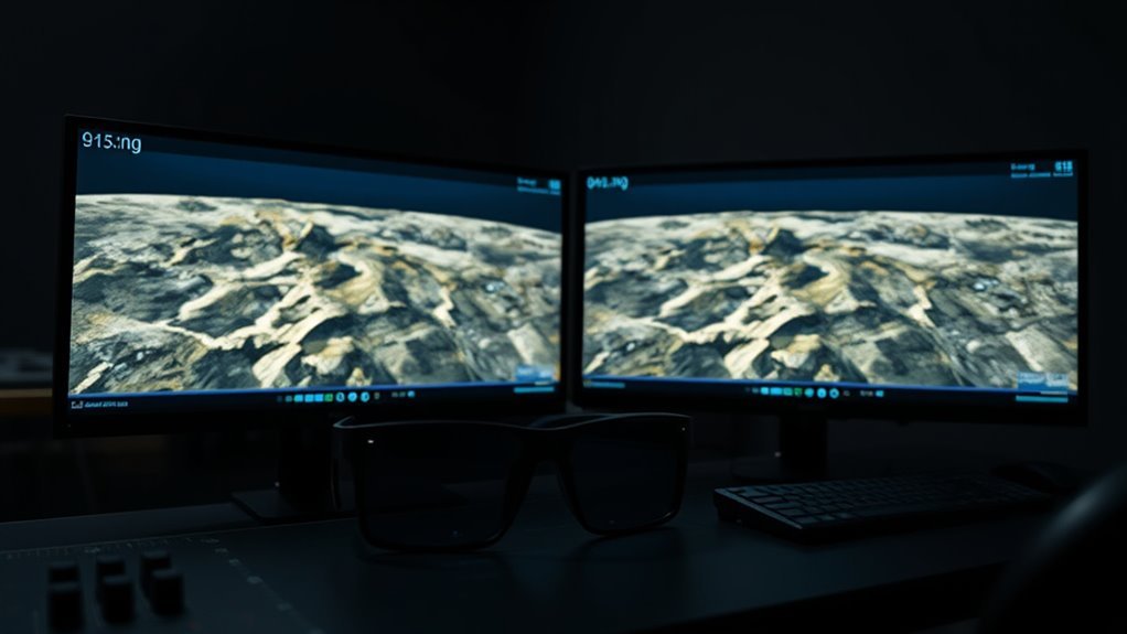
Creating a drone orthomosaic in Metashape involves more than joining aerial photographs. You need sharp, overlapping images, a reliable elevation surface, and accurate georeferencing. If you also want stereoscopic viewing, Metashape Professional lets you examine overlapping images in 3D, measure terrain features, and inspect details that are difficult to interpret on a flat map.
Quick Answer
To create a drone orthomosaic in Metashape, import overlapping aerial photos, align the images, add ground control points if available, optimize the cameras, build an elevation model, and generate the orthomosaic. Check accuracy using independent checkpoints, review the reconstructed surface in stereoscopic mode if needed, and export the finished map as a georeferenced GeoTIFF.
At a Glance
| Difficulty | Intermediate; advanced for survey-grade delivery |
| Tools Needed | Overlapping drone photographs, Agisoft Metashape Professional, and suitable computer hardware. Surveyed control points and compatible stereo equipment are optional according to project requirements. |
What Is a Drone Orthomosaic?
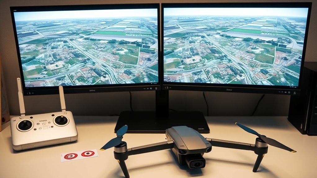
A drone orthomosaic is a map created from overlapping aerial photographs that have been corrected for camera perspective and changes in surface elevation.
Unlike a simple photo collage, an orthomosaic uses photogrammetry to place image features within a consistent map projection. Each pixel has a geographic position, allowing the finished image to support spatial measurements and GIS analysis.
Agisoft Metashape aligns the source images, estimates camera positions, reconstructs the surface, and projects the photographs onto that surface.
The process is called orthorectification. It reduces the distortions caused by camera angle and terrain height.
The resulting image can support applications such as:
- Construction site monitoring and progress documentation.
- Agricultural mapping and crop assessment.
- Land surveying and environmental monitoring.
- Infrastructure inspection and urban planning.
- Disaster assessment and landscape analysis.
However, an important distinction exists between an orthomosaic and a stereoscopic model.
An orthomosaic is a two-dimensional map. Stereoscopic viewing uses overlapping images to create a perception of depth. It helps you interpret terrain and measure features, but it does not turn the exported orthomosaic into a three-dimensional file.
For elevation analysis, retain the digital elevation model (DEM) or another suitable 3D dataset alongside the orthomosaic.
Why Use Metashape for Orthomosaics?
Agisoft Metashape combines image alignment, camera calibration, surface reconstruction, and georeferenced map production in one workflow.
Its Professional edition also provides ground control, independent checkpoints, elevation models, stereoscopic measurements, and GIS-compatible exports.
These tools make it suitable for projects that require both detailed visual maps and measurable spatial data.
Survey-Grade Accuracy
Metashape can support survey-grade mapping when the image capture, ground measurements, coordinate systems, and processing settings meet the project’s accuracy requirements.
Ground Control Points (GCPs) connect features visible in the aerial images to surveyed real-world coordinates.
RTK and PPK positioning can provide more accurate camera locations than ordinary drone GPS. These positions help constrain the photogrammetric model.
However, neither RTK/PPK nor GCPs automatically guarantee a specific accuracy.
The actual result depends on image quality, survey equipment, calibration, control distribution, and the reconstructed surface.
For dependable results:
- Use accurate reference coordinates and the correct coordinate system.
- Distribute control points across the project area.
- Reserve separate surveyed points for independent accuracy checks.
- Review horizontal and vertical errors before accepting the result.
This combination supports applications such as construction surveys, precision farming, and environmental monitoring.
Fast Orthomosaic Workflow
Metashape automates many demanding photogrammetry operations, including feature matching, camera alignment, point cloud generation, and orthomosaic production.
Its batch-processing and Python scripting capabilities also help with repeated projects and large image collections.
Processing speed depends on image count, image resolution, computer hardware, and the selected quality settings.
A quick preliminary alignment can reveal gaps or incorrectly aligned cameras before you spend time on detailed surface reconstruction.
Metashape Professional also supports multispectral and thermal imagery. These inputs can extend the workflow into vegetation analysis, temperature mapping, and related applications when suitable sensors and calibration data are available.
For final delivery, GeoTIFF preserves the orthomosaic’s geographic reference and allows it to be opened in GIS software.
Prepare Drone Photos for Metashape Orthomosaics
Good orthomosaics begin with good source photographs. Image overlap, camera settings, lighting, and complete coverage determine how reliably Metashape can align the dataset.
Before processing, review the photographs and confirm that important areas appear in several overlapping frames.
Flight Overlap Settings
Flight overlap determines how much ground appears in neighboring photographs. Greater overlap provides more opportunities to identify matching features and reconstruct surface geometry.
Agisoft’s aerial survey recommendations advise against using less than 80% forward overlap or 60% side overlap for good-quality results.
For standard aerial mapping, use these values as a planning baseline rather than assuming one flight configuration suits every location.
- Forward overlap: Aim for at least 80% between consecutive photographs.
- Side overlap: Use at least 60%, increasing it where necessary.
- Challenging sites: Higher side overlap, such as 85%, may help where vegetation, complex terrain, or weak image texture makes matching difficult.
A regular grid flight provides systematic coverage. A consistent camera angle and flight altitude also help maintain predictable image scale.
Lower flight altitude generally improves ground resolution, but it reduces the area covered by each photograph and increases image count.
For complex structures or steep terrain, additional oblique photographs may help reconstruct surfaces that a straight-down camera cannot see clearly.
Image Quality Checks
Sharp images are essential because photogrammetry relies on matching visible details between photographs.
Inspect the dataset for motion blur, poor focus, glare, deep shadows, and missing coverage before alignment.
Metashape includes an Estimate Image Quality function. Its quality value represents image sharpness, not the final map’s positional accuracy.
The Agisoft Metashape user manual recommends disabling images with quality values below 0.5.
An image scoring 0.8 may be sharper than one scoring 0.5, but 0.8 is not a mandatory processing threshold.
To check image quality:
- Open the Photos pane.
- Switch to its detailed view.
- Select the photographs you want to evaluate.
- Right-click and choose Estimate Image Quality.
- Review the Quality column and inspect suspicious images visually.
Disable unusable images only after confirming that the remaining photographs still cover the required area.
| Check | Target |
|---|---|
| Forward overlap | At least 80% |
| Side overlap | At least 60% |
| Estimate Image Quality | Review images below 0.5 |
| ISO | 100–200 when lighting permits |
| Shutter speed | 1/800s or faster when appropriate |
These camera settings are practical starting points, not requirements for every drone. Adjust them to match lighting, sensor characteristics, and aircraft movement.
Camera Setup Tips
A consistent camera setup improves alignment and reduces avoidable image differences.
Lock the focus once the intended subject distance is established. Avoid changing zoom or focal length during the mapping flight unless the processing workflow accounts for those changes.
For reliable results:
- Keep the camera angle consistent during a standard mapping flight.
- Use manual focus or locked autofocus when suitable.
- Choose a fast enough shutter speed to avoid motion blur.
- Keep ISO low enough to limit unnecessary image noise.
- Prefer consistent lighting and avoid strong glare or changing shadows.
Overcast conditions often provide more even illumination, although adequate light is still necessary for sharp images.
Before leaving the site, confirm that the full project boundary is covered. Missing imagery cannot be recovered through processing alone.
Add GCPs for Accurate Orthomosaics
Ground Control Points are identifiable ground targets with known coordinates. They help Metashape position and scale the reconstructed model within the required coordinate system.
Survey the targets accurately and place them where they are visible in multiple photographs.
Distribute them across the corners, edges, and interior of the project rather than clustering them in one location.
| GCP Count | Use Case |
|---|---|
| 3+ | Possible starting point for a small controlled site; not a universal accuracy guarantee |
| 5–10 | Planning range for some projects; increase according to site size and survey requirements |
| Even spread | Include boundaries, corners, and interior areas |
| <2 cm RMSE | Project-specific accuracy target, not an automatic Metashape result |
The appropriate number of points depends on the site’s shape, terrain, image geometry, and required accuracy.
Do not use every surveyed point as control. Keep some as independent checkpoints so you can test the reconstruction against coordinates that did not influence the adjustment.
Agisoft’s control and checkpoint guidance recommends having at least three to five points available for accuracy assessment.
To add GCPs in Metashape:
- Open the Reference pane.
- Import the file containing surveyed marker coordinates.
- Select the correct coordinate system and coordinate columns.
- Specify the known measurement accuracy.
- Open the photographs containing each marker.
- Place each marker precisely on its visible target in multiple images.
- Enable the markers intended as control points.
- Leave independent checkpoints disabled as control observations.
- Update the reference information and optimize the camera alignment.
Agisoft recommends manually marking each target in at least three photographs before using automatic marker refinement.
Also confirm that the horizontal coordinate system and vertical datum are consistent across camera positions, GCPs, and the final deliverables.
An incorrect altitude reference can create a systematic height shift even when the map looks visually correct.
Build the Orthomosaic in Metashape
The standard workflow runs from image alignment to surface reconstruction, orthomosaic generation, and export.
The following steps assume you are working in Agisoft Metashape Professional with overlapping aerial photographs.
Agisoft’s official aerial processing workflow with GCPs explains the underlying alignment, calibration, reference, and surface-generation procedures.
Step 1: Create a Project and Import Photos
Open Metashape and create a new project. Save it in PSX format so you can store the processing data required for the workflow.
Select Workflow > Add Photos and import the complete aerial image set.
Check that the image metadata, camera information, and available location coordinates have loaded correctly.
Step 2: Check Camera Calibration
Open Tools > Camera Calibration.
Confirm the camera model, focal length, and pixel size. Metashape can estimate calibration parameters automatically from suitable image metadata.
If the project contains images from different cameras or separate capture configurations, organize them into suitable calibration groups.
Incorrect calibration can introduce systematic distortion into the reconstruction.
Step 3: Align the Photographs
Select Workflow > Align Photos and choose the appropriate alignment settings.
Metashape detects matching image features, estimates camera positions, and generates a tie point cloud.
Inspect the result before moving forward.
Look for unaligned photographs, isolated camera positions, broken flight strips, and missing coverage.
If a group of images fails to align, investigate overlap and image quality rather than immediately increasing reconstruction quality.
Step 4: Add Control Points and Optimize Cameras
Import the surveyed GCP coordinates and place the markers on the corresponding photographs.
Set the correct reference accuracy and optimize the camera alignment.
Camera optimization refines the estimated camera parameters and model geometry using the available observations.
Review residual errors and the independent checkpoints before continuing.
Step 5: Build the Point Cloud or Depth-Based Surface
Select Workflow > Build Point Cloud if a detailed point cloud is required.
Choose processing quality and filtering settings that match the available hardware and the surface detail you need.
Moderate filtering can provide a useful starting point. More aggressive filtering may remove noise but can also remove important small features.
For a standard terrain orthomosaic, a separate dense point cloud is not always mandatory. Metashape can also build a DEM from supported sources such as depth maps.
Step 6: Build the Digital Elevation Model
Select Workflow > Build DEM.
Choose the appropriate source data and coordinate system.
The DEM represents elevation as a regular grid of height values. Metashape uses this surface to correct the aerial photographs for terrain-related distortion.
A digital surface model (DSM) includes visible surfaces such as buildings and vegetation. A digital terrain model (DTM) represents the underlying ground and requires suitable ground classification or other terrain data.
Choose the surface according to the project. A poor elevation model can create distortions even when image alignment is accurate.
Step 7: Generate the Orthomosaic
Select Workflow > Build Orthomosaic.
Choose the desired projection and coordinate system, then select the appropriate surface.
For ordinary aerial mapping, the DEM is a common choice. A detailed mesh may be more suitable where buildings and other complex structures require closer control of surface geometry.
Review the output resolution and blending settings before starting processing.
When the operation finishes, open the Ortho view and inspect the entire map.
Check building edges, road markings, vegetation boundaries, and areas where photographs meet.
Step 8: Save and Prepare the Deliverables
Save the completed project and preserve the source photographs, reference data, elevation model, and final orthomosaic.
Keep the processing report with the deliverables when accuracy must be documented.
You now have a georeferenced map ready for quality checks, optional stereo review, and export.
Check Orthomosaic Accuracy and Errors
Orthomosaic accuracy should be evaluated using independent surveyed checkpoints, not simply by checking whether the image looks sharp.
Ground control residuals show how well the adjusted model fits its control observations. Checkpoints provide a more independent test because their coordinates were not used to constrain the adjustment.
Ground Control Points anchor orthomosaic accuracy, while checkpoints verify the map’s measurement reliability.
Review horizontal and vertical errors separately. Root Mean Square Error (RMSE) summarizes the size of the coordinate differences across the evaluated points.
A low GCP residual does not, by itself, prove that the entire orthomosaic meets a specified mapping standard.
Checkpoints should be distributed across the mapped area and measured with equipment appropriate to the required accuracy.
Understand Ground Sample Distance
Ground Sample Distance (GSD) describes how much ground is represented by one image pixel.
It depends on camera sensor characteristics, focal length, and distance from the camera to the ground.
For example, the original planning estimates of roughly 0.5–1 inch per pixel at 100 feet and approximately 2 inches per pixel at 400 feet are camera-dependent examples, not universal results.
A higher flight altitude generally produces a larger GSD when the camera configuration remains unchanged.
Remember that GSD is not the same as positional accuracy. A map can have small pixels and still be shifted from its correct geographic position.
Inspect the Reconstructed Surface
Look for surface bumps, holes, warped buildings, and unexpected elevation changes.
These defects can indicate poor image matching, weak control geometry, inaccurate markers, or incorrect surface reconstruction.
Inspect the tie points and camera positions before deleting anything.
Metashape’s tie point filtering tools can help identify unreliable matches, but removing too many points can weaken the reconstruction.
After meaningful changes, optimize the cameras again and reassess the independent checkpoints.
Review the Orthomosaic in 3D
Stereoscopic viewing helps you examine terrain and structures with a perception of depth that is unavailable in a flat orthomosaic.
In Metashape Professional, you can review overlapping photographs as stereo pairs and use 3D measurement and vectorization tools.
This is particularly useful for examining embankments, gullies, roof edges, breaks in slope, and other elevation-dependent features.
Configure Stereoscopic Display Mode
Open Tools > Preferences and locate the Stereoscopic Display setting in the General tab.
Metashape supports several display modes:
- Anaglyph: Uses compatible colored glasses to separate the left and right views.
- Hardware: Requires a compatible professional stereoscopic display system and graphics hardware supporting quad-buffered stereo.
- Vertical Split: Displays the stereo views in a vertically divided arrangement.
- Horizontal Split: Displays the stereo views in a horizontally divided arrangement.
Choose the mode that matches your display equipment.
Follow Agisoft’s stereo pair selection and navigation instructions when configuring the viewing environment.
Open and Review a Stereo Pair
Once the photographs have been aligned, switch to Model > View Mode > Stereo Mode.
Open the Photos pane, select two overlapping photographs, and choose Look Through from the context menu.
The selected pair appears in the Model view.
Use Lock Images if you want to prevent the selected pair from changing while navigating.
You can then examine depth relationships and use the available ruler and drawing tools to inspect or trace spatial features.
Metashape Professional also provides object and terrain navigation modes for stereoscopic work.
If the 3D cursor does not appear, confirm that the Model view is using perspective mode rather than orthographic mode.
What Should You Inspect in Stereo?
Compare the stereo representation with the reconstructed surface and finished orthomosaic.
Pay particular attention to:
- Elevation changes along embankments and gullies.
- Building edges and roof geometry.
- Surface discontinuities and unexplained bumps.
- Vegetation that may obscure the underlying ground.
- Features that appear displaced or distorted in the orthomosaic.
Stereo review can reveal interpretation problems, but it is not a replacement for checkpoint-based accuracy assessment.
For elevation measurements, use an appropriately georeferenced model and verify the relevant vertical reference.
Export Orthomosaics to GIS and CAD
GeoTIFF is the standard practical choice for delivering a georeferenced orthomosaic to GIS software.
It stores raster image data together with geographic reference information, allowing the map to be placed correctly in software such as QGIS and ArcGIS.
Export the Orthomosaic as GeoTIFF
In Metashape, select File > Export Orthomosaic.
Then:
- Select the required coordinate system.
- Choose TIFF/GeoTIFF as the output format.
- Set the appropriate export resolution.
- Review the output dimensions and coverage.
- Enable any additional world or KML files required by the receiving workflow.
- Export the file and verify it in the target GIS application.
Use a coordinate system suitable for the project. A local projected system is generally more practical for distance and area measurements than geographic coordinates expressed only as latitude and longitude.
Do not assume that reducing the export pixel size will improve the original imagery. Export resolution cannot recover detail that was never captured.
Prepare Data for CAD
An orthomosaic is raster imagery, while CAD drawings commonly use vector geometry.
The orthomosaic should therefore be exported as GeoTIFF and brought into the CAD environment as a referenced raster when supported.
If you need editable points, boundaries, or other traced features, export the vector data separately.
Metashape’s vectorization tools allow shapes created in Model or Ortho view to be exported in formats including DXF and SHP.
Select File > Export > Export Shapes and choose the required format and coordinate system.
DWG may be used in downstream CAD workflows, but it should not be confused with Metashape’s direct orthomosaic raster export.
Export Additional Mapping Products
Depending on the project, deliver the orthomosaic alongside:
- A DEM in GeoTIFF format for elevation analysis.
- A point cloud for three-dimensional inspection.
- Contours or other vector features for GIS and CAD.
- A processing report documenting the reference information and accuracy checks.
For large exports, use compression or split the output into blocks where appropriate.
Metashape also supports BigTIFF for raster files that exceed the standard TIFF size limit.
Agisoft’s aerial processing and export guide without GCPs documents the supported raster formats and export options.
Fix Common Orthomosaic Problems
Most orthomosaic defects originate from source imagery, image alignment, georeferencing, or the elevation surface.
Identify the affected processing stage before rebuilding the entire project.
Photographs Fail to Align
Insufficient overlap, blurred images, weak surface texture, and incorrect camera information can prevent successful alignment.
Start by reviewing the unaligned photographs and the camera calibration groups.
Confirm that neighboring images contain recognizable common features.
If a flight strip lacks adequate coverage, collecting additional images may be more effective than changing processing settings.
The Orthomosaic Contains Gaps
Gaps can result from missing photographs, failed alignment, or incomplete surface reconstruction.
Compare the gaps with the original flight coverage.
If the required area was never photographed, a new flight is the dependable solution.
If suitable photographs exist, inspect alignment and the DEM before rebuilding the orthomosaic.
Buildings or Roads Look Distorted
Distorted edges often indicate problems with the reconstructed surface, image alignment, or orthorectification.
Review the camera positions and inspect the DEM or mesh around the affected features.
Where complex building geometry is important, a suitable detailed surface may produce better results than a simplified elevation model.
Seams, Ghosting, or Color Differences Appear
Moving objects, changing lighting, and differences between overlapping photographs can create visible seams or duplicated features.
Metashape provides manual seamline editing so you can select the source images used in a particular area.
Agisoft’s orthomosaic seamline editing guide explains how to assign images to selected patches and apply the changes.
Use color calibration when appropriate for datasets captured under noticeably different lighting conditions.
Remember that improving the visual appearance does not automatically correct positional errors.
GCP or Checkpoint Errors Are Too High
Large residuals may indicate incorrect coordinates, misplaced markers, inconsistent coordinate systems, or poor image geometry.
Check the marker positions in the original photographs.
Confirm the coordinate reference system and vertical datum, then review the accuracy values assigned to the observations.
Optimize the cameras and evaluate the independent checkpoints again.
Do not remove a checkpoint solely because it makes the reported accuracy look worse. Investigate the reason for the discrepancy first.
Stereoscopic Viewing Does Not Work
Check that the selected display mode matches the available hardware and glasses.
For hardware stereo, confirm that the graphics system supports quad-buffered stereo and that the display is compatible.
If stereo pairing works but the 3D cursor is missing, check the perspective setting in Model view.
For a simpler starting configuration, use an appropriate anaglyph or split-screen setup.
Frequently Asked Questions
How Does Stereoscopic Viewing Improve Orthomosaic Interpretation?
Stereoscopic viewing adds a perception of depth to overlapping aerial photographs. It helps you distinguish terrain elevations, building shapes, and surface boundaries that may be difficult to interpret in a flat orthomosaic. It supports visual inspection and feature measurement but does not replace independent accuracy checks.
Which Monitor and Glasses Work Best for Stereoscopic Map Review?
Choose a monitor and glasses that match the stereoscopic display mode supported by your computer and Metashape. Anaglyph viewing uses compatible colored glasses, while hardware stereo requires professional equipment supporting quad-buffered stereo. A high-resolution IPS or OLED monitor alone does not guarantee compatibility with active shutter glasses.
Can Orthomosaics Be Used for Real-Time Field Decisions?
Orthomosaics can support rapid field decisions, but they are not automatically real-time products. Crews can use recently processed maps for construction monitoring, agriculture, environmental assessment, infrastructure inspection, and disaster response. Their usefulness depends on processing time, data accuracy, communication access, and how quickly site conditions change.
How Often Should Drone Orthomosaics Be Updated?
Update frequency should match how quickly the mapped area changes. Active construction sites may need weekly surveys, while less dynamic landscapes may only require monthly or periodic updates. Additional mapping may be necessary after storms, flooding, excavation, or major environmental changes. Keep flight settings and coordinate references consistent when comparing surveys over time.
What Are the Best Uses for Stereoscopic Orthomosaic Analysis?
Stereoscopic analysis is useful for terrain interpretation, aerial mapping, environmental monitoring, urban planning, agricultural assessment, archaeological surveys, infrastructure inspection, and disaster response. It helps analysts interpret elevation and feature boundaries using overlapping photographs. For precise measurements, the supporting georeferenced model and independent accuracy checks remain essential.
Can Metashape Create an Orthomosaic Without Ground Control Points?
Yes, Metashape can create an orthomosaic without GCPs when suitable image positioning and scaling information is available. Accurate RTK or PPK camera coordinates can support georeferencing. However, independent surveyed checkpoints provide a stronger assessment of absolute accuracy than relying on camera coordinates alone.
Does Stereoscopic Viewing Turn an Orthomosaic Into a 3D Model?
No, stereoscopic viewing does not convert the orthomosaic itself into a 3D model. The orthomosaic remains a two-dimensional georeferenced raster. Stereo viewing provides depth perception from overlapping images, while separate products such as a DEM, point cloud, or mesh preserve three-dimensional information for further analysis.
Conclusion
A reliable drone orthomosaic in Metashape begins with sharp photographs, sufficient overlap, accurate camera calibration, and well-distributed reference data. Build the correct elevation surface, assess independent checkpoints, and inspect the map before exporting it.
Stereoscopic viewing adds useful depth interpretation, especially for complex terrain and structures. Keep the orthomosaic, elevation data, and accuracy report together so the final results remain useful for GIS, CAD, and future mapping comparisons.
Sources
- Agisoft — Aerial Survey Tips: Recommended forward and side overlap, image capture, and lighting guidance.
- Agisoft Metashape User Manual, Version 2.3: Image quality estimation and the recommended 0.5 threshold.
- Agisoft — Aerial Data Processing With GCPs: Camera calibration, alignment, control markers, optimization, DEM generation, and orthomosaic processing.
- Agisoft — Control and Check Points for Aerial Surveys: Marker placement, reference settings, and independent accuracy assessment.
- Agisoft — Aerial Data Processing Without GCPs: RTK/PPK-based workflow, DEM and orthomosaic export, and supported raster formats.
- Agisoft — Stereo Pair Selection, Measurements and Navigation: Stereoscopic display modes, hardware requirements, navigation, and stereo measurements.
- Agisoft — Vectorization Tools: Creating and exporting vector features in GIS and CAD-compatible formats.
- Agisoft — Orthomosaic Seamline Editing: Correcting visible stitching artifacts and selecting source images for patches.
