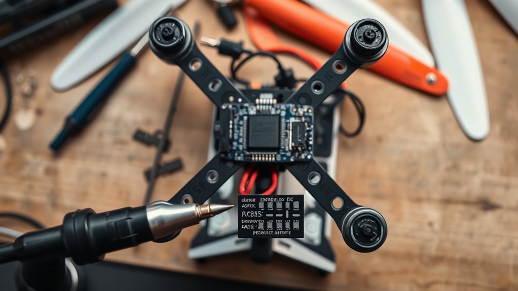
To connect an ELRS controller to Betaflight, the ELRS receiver is wired to a free UART on the flight controller, with RX to TX and TX to RX, plus correct power and ground. The transmitter and receiver must share the same bind phrase and be bound at least 0.5 meters apart. In Betaflight, Serial RX is enabled on that UART and the receiver protocol is set to CRSF. Stick movement should then appear, with further setup steps available below.
Wire the ELRS Receiver to the Flight Controller
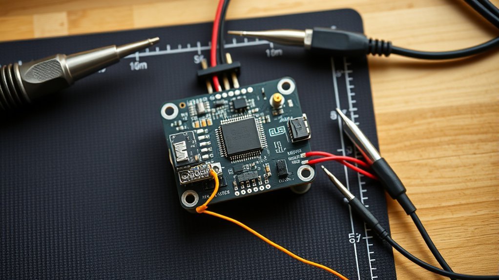
Consult the flight controller manual’s wiring diagram before soldering the ELRS receiver to confirm pad functions and voltage requirements. This step prevents misrouting and preserves system autonomy.
The RX pin on the receiver should be wired to an unused UART TX pad on the flight controller. The TX pin should be wired to the matching UART RX pad. Power and ground must follow the manual exactly.
Wire the receiver’s RX to an unused UART TX, TX to RX, and follow the manual exactly for power and ground.
Each wire should be trimmed, tinned, and secured with clean solder joints to reduce resistance, signal loss, and vibration-related failure. For TBS Crossfire or ELRS protocols, the selected UART should not conflict with MSP, SmartPort, telemetry, or other active peripherals. A dedicated serial path keeps control authority clear and uncompromised.
After installation, the receiver should be checked for power and normal function. Visual indicators, such as LEDs, can confirm startup state.
If necessary, the receiver manual should be consulted for verification methods before Betaflight configuration begins.
Bind Your ELRS Controller First
Before binding, ELRS compatibility should be confirmed between the transmitter and receiver.
Both devices must then be configured with the same bind phrase to enable automatic pairing.
The transmitter and receiver manuals should be referenced for model-specific steps and binding indicators.
Confirm ELRS Compatibility
To confirm ELRS compatibility, the controller and receiver should first be verified against the same major ExpressLRS firmware branch, such as 4.x, and checked for matching hardware support. This step helps confirm ELRS compatibility before Betaflight setup and prevents protocol mismatches that restrict reliable control.
The firmware version on both devices should align with the receiver’s specifications and the transmitter module’s supported target.
Next, the binding procedure should be completed exactly as defined in the receiver manual, while keeping at least 0.5 meters between transmitter and receiver to reduce interference.
The ELRS LUA script can then be used to verify connection status through its visual indicators.
Final confirmation should be performed in Betaflight Configurator by moving sticks or toggling switches and observing receiver response on the channel bars in real time.
Set Matching Bind Phrase
Set the same bind phrase on both the ELRS transmitter and receiver so they can auto-bind after flashing. This step-by-step guide helps bind ELRS cleanly and without dependence on manual pairing. In ExpressLRS Configurator, the operator enters one unique phrase before flashing both devices.
- Choose a unique bind phrase, ideally 8-16 characters long.
- Enter the identical phrase in transmitter and receiver firmware settings.
- Flash both devices through ExpressLRS Configurator with that saved phrase.
- Verify binding through receiver LEDs and transmitter control response.
If the phrase must change later, the user can re-flash firmware or use the receiver WebUI when supported.
Successful verification confirms secure linking and restores direct control authority, giving the pilot a freer, more self-directed setup for Betaflight configuration and operation.
Enable Serial RX on the Correct UART
In the Ports tab of Betaflight Configurator, the receiver UART should be identified by matching the flight controller wiring diagram to the physical receiver connection, such as UART2.
Serial RX is then enabled only on that UART row, with no other function assigned there to prevent port conflicts.
After saving and rebooting, the Receiver tab is used to verify that stick and switch inputs register correctly.
Find The Receiver UART
Locate the receiver UART by checking the flight controller wiring diagram in the manual and matching the receiver signal wire to its assigned RX pad or UART. This confirms where the receiver is connected and prevents wasted configuration steps.
In Betaflight, the operator should open the Ports Tab and identify the corresponding UART row before making any changes. Each UART supports one primary function, so the selected row must not already be occupied by MSP, GPS, or telemetry.
Firmware compatibility should also be confirmed, with Betaflight 4.4.0 or newer preferred for modern receiver protocols and freer system performance.
- Check the manual for the labeled RX pad.
- Match the signal wire to its UART number.
- Verify the UART is unused by other functions.
- Confirm firmware supports the intended receiver protocol.
This isolates the correct port cleanly.
Enable Serial RX
Afterward, the operator should save the configuration and reboot the flight controller so the change becomes active.
Once Betaflight reconnects, the next verification occurs in the Receiver Tab. There, stick movements from the controller should register cleanly and responsively. If channel activity appears, the system is communicating correctly.
This confirms the attempt to enable Serial RX succeeded and the pilot retains direct, unrestrained command over the craft in flight.
Avoid UART Conflicts
A common source of receiver setup failure is a UART conflict. In Betaflight, freedom from hidden misconfiguration begins by assigning Serial RX only to the UART actually wired to the receiver. The flight controller manual should be consulted first to confirm the correct RX/TX pads and their matching UART row.
- Verify the receiver’s wiring and identify its assigned UART from the board documentation.
- In the Ports tab, enable Serial RX only on that specific UART row.
- Disable overlapping functions, especially MSP or other peripherals, on the same UART.
- Save the configuration and reboot the flight controller after every change.
Only one active function should occupy each UART row. If another device already uses that port, reassignment is required.
This disciplined approach prevents overlap, restores control authority, and enables reliable receiver communication.
Set the Receiver Protocol to CRSF
After reboot, open the Receiver tab to confirm the configuration has been accepted by Betaflight.
This verifies that the system is aligned with the selected protocol before any further troubleshooting or input validation proceeds.
Test ELRS Stick Inputs in Betaflight
- Confirm the correct UART has Serial RX enabled in the Ports tab.
- Verify the ELRS Receiver remains bound and powered before moving controls.
- Move sticks and toggle switches; observe matching channel bar movement in Betaflight.
- Check that the selected receiver protocol remains CRSF, matching the previous setup.
Responsive movement across roll, pitch, throttle, yaw, and auxiliary channels indicates that communication is active and the link is functioning as intended.
If no motion appears in the Betaflight interface, the installer should recheck wiring integrity, binding status, and protocol selection.
Accurate input detection is the gateway to a more independent, fully liberated flight experience.
Troubleshoot ELRS Not Showing in Betaflight
Next, check binding status. The transmitter and receiver should show successful pairing through their normal LED or audible indicators.
If binding has failed, Betaflight will not display channel activity. Firmware compatibility must also be verified on both devices; mismatched ELRS versions can block communication even when wiring appears correct.
Finally, if no movement appears in the Receiver tab, separate the transmitter and receiver by at least 0.5 meters during testing. This prevents overload at close range and restores clean input visibility and control.
Frequently Asked Questions
How Do I Set up an ELRS Receiver in Betaflight?
Configure ELRS setup by wiring receiver TX/RX to a free UART RX/TX, enabling Serial RX, selecting CRSF in Betaflight configuration, binding transmitter and receiver with matching phrase, then verifying active channel movement in the Receiver tab.
How to Connect Controller to Betaflight?
Connect the flight controller via data-capable USB, open Betaflight, select the COM port, and connect. Complete controller configuration in Ports and Configuration tabs, verify Receiver inputs, and confirm firmware updates before flight for autonomous, reliable operation.
How to Bind ELRS Receiver to Controller?
Like opening a gate, the binding process requires matching firmware binding phrases on transmitter and receiver configuration. Flash via ExpressLRS Configurator, enable LOCK_ON_FIRST_CONNECTION, power both devices nearby, then verify LED indicators confirm successful pairing.
Which Flight Controllers Are Compatible With Betaflight?
Most STM32-based F4, F7, and H7 flight controllers are compatible with Betaflight. One should verify manufacturer targets, required flight controller features, UART availability, OSD support, memory capacity, and current Betaflight updates before selecting hardware.
Conclusion
By completing wiring, binding, UART configuration, CRSF selection, and input verification, the ELRS controller can be connected to Betaflight reliably. If stick movement does not appear, systematic troubleshooting of power, signal wiring, UART choice, and receiver firmware should isolate the fault. Once configured correctly, the link provides low-latency, stable control. Even in an age of telegraphs, such precision would have felt extraordinary. Careful sequencing and verification remain the most efficient path to a working ELRS-Betaflight setup overall.
