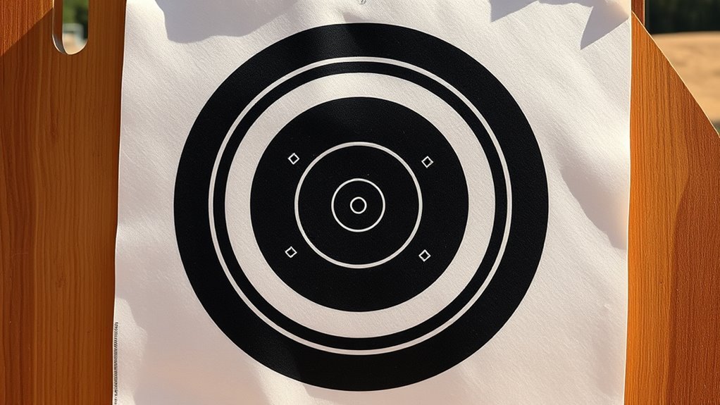
The best target for adjusting a rifle scope has a clear aiming point, strong contrast, and markings that are easy to read. Bullseye, grid, and dot designs offer different ways to view shot placement. Choosing the right layout depends on the target distance, visibility, and the information you need from the printed markings.
Quick Answer
A high-contrast bullseye with a clearly marked grid is a practical all-purpose target for rifle scope zeroing. The bullseye provides an easy-to-see center, while the grid gives a measurable reference for shot placement. Dot targets offer a simpler alternative, and concentric scoring rings help show group size and dispersion.
Key Takeaways
- Bullseye targets provide a recognizable center and concentric rings for reading shot groups.
- Grid targets provide a measurement scale, but printed spacing must be accurate.
- Small dot targets have simple layouts that make individual aiming points easy to identify.
- A target’s size and visibility should suit the viewing distance and available lighting.
- MOA, MRAD, parallax, and zero-stop features depend on the particular optic.
Best Target Images for Scope Zeroing
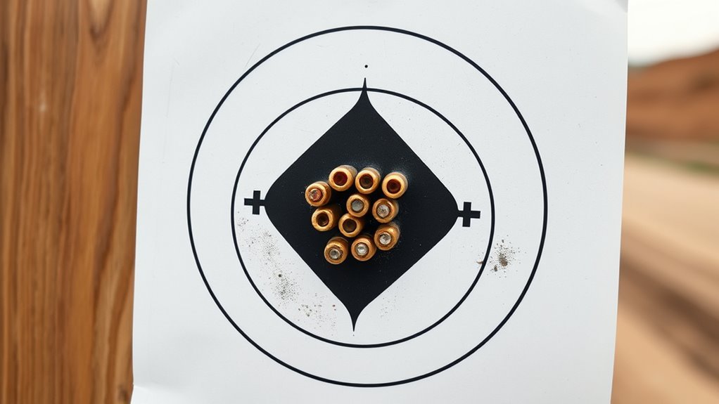
The most useful scope zeroing target images have an unmistakable center and markings that remain readable through the optic. Different designs emphasize different information, so there is no need for every target to look the same.
The main options are:
- Bullseye targets: A central circle and surrounding rings provide a familiar reference for evaluating shot placement.
- Grid targets: Evenly spaced horizontal and vertical lines provide a measurement reference for elevation and windage.
- Dot targets: Individual dots provide separate aiming areas without a crowded central design.
- Reactive targets: A visible color change around an impact makes holes easier to identify.
- Scoring-ring targets: Concentric circles help show group size and shot dispersion.
A combination bullseye-and-grid target brings the two main visual references together.
The Texas Parks and Wildlife sighting-in guide identifies a centered bullseye with an underlying one-inch grid as a suitable paper target format.
Calibrated markings can also provide a reference for comparing impact positions at different distances. However, markings on paper should not be mistaken for a universal bullet-trajectory chart.
Trajectory depends on the rifle, ammunition, sight height, and distance. A target image alone cannot establish those relationships.
[Amazon Products Picked for You]

Bullseye: DARK RED ½ MOA, LIGHT RED 1 MOA, GRAY 1.5 MOA, BLACK RING 2 MOA


Instantly see your SHOTS BURST BRIGHT FLUORESCENT YELLOW upon impact, spend more time shooting and less time checking your target.
Why a Bullseye Makes Scope Adjustments Easier
A bullseye target provides a single, recognizable center surrounded by concentric rings. Its simple layout makes the aiming reference easy to locate and helps separate the center from the rest of the target.
The rings also offer a visual guide to shot dispersion, although they are not necessarily calibrated to a particular scope adjustment.
Three features make bullseye targets useful:
- Center reference: The central mark provides a fixed point of aim.
- Ring spacing: Concentric circles help show how impacts are distributed around the center.
- Consistent layout: Reusing the same target design makes it easier to compare results from separate sessions.
Black markings on a white background are common because they provide strong contrast. Fluorescent centers can also help distinguish the aiming point from the surrounding paper.
A bullseye should be large enough to see without covering so much of the target that its center becomes difficult to identify.
How Grid Lines Help Zero Your Rifle Scope
Grid lines provide a measurement reference behind the aiming point. Their main advantage is that they show horizontal and vertical displacement against a consistent scale.
Unlike decorative background lines, a calibrated grid has known spacing. This makes the printed pattern useful for interpreting the relationship between point of aim and point of impact.
Grid Lines for Alignment
Intersecting lines provide a clear visual reference for the scope’s reticle. A central intersection identifies the target center, while surrounding lines establish horizontal and vertical directions.
The main features to look for are:
- A clearly marked central intersection.
- Consistent spacing across the sheet.
- Grid lines that remain visible without overwhelming the aiming point.
- Enough open space to distinguish individual bullet holes.
A grid can also help distinguish a consistent impact pattern from an isolated shot.
However, printed lines must represent their stated measurements. A grid that has been stretched or resized during printing no longer provides the intended scale.
Measuring POI With Grids
Point of impact, or POI, means where a bullet strikes the target. Point of aim, or POA, means the location identified by the reticle.
A grid makes the difference between those two positions easier to see.
For example, an impact above the center has a vertical offset. An impact to the left has a horizontal offset. An impact above and left of center has both.
The grid shows physical spacing on the paper. MOA and MRAD describe angular measurements, so the two should not be treated as interchangeable units.
Repeated patterns may provide useful information about a scope’s tracking or the consistency of the shooting setup. A single unusual impact, however, is not enough to establish a mechanical fault.
How Crosshairs Show Bullet Impact
Crosshairs are part of the scope’s reticle, not the paper target. Their intersection provides the central aiming reference, while the target records the actual point of impact.
The relationship between the two is the basis of scope zeroing.
A reticle identifies the intended aiming point; the target records the actual impact location.
Three terms explain the basic relationship:
- Point of aim: The intended location identified by the reticle.
- Point of impact: The actual location of the bullet hole.
- Zero: The established relationship between the two at a chosen distance.
Elevation refers to vertical adjustment. Windage refers to horizontal adjustment.
The direction markings on a scope’s turrets normally describe the intended movement of the point of impact, rather than the apparent movement of the reticle itself.
Adjustment systems vary between models, so the manufacturer’s instructions remain the correct reference for the particular optic.
Leupold’s riflescope sighting-in guide explains the relationship between turret markings, impact location, and the scope’s zero setting.
How to Read Elevation for Rifle Scope Zeroing
Elevation describes the vertical relationship between the point of impact and point of aim. A marked target makes that relationship easier to recognize.
Scope adjustment values are commonly expressed in minutes of angle (MOA) or milliradians (MRAD, also called MIL). The actual increment depends on the scope.
| Target or scope reference | Meaning |
|---|---|
| Above POA | Impact is vertically above the aiming point |
| Below POA | Impact is vertically below the aiming point |
| 1/4 MOA | A common angular adjustment increment |
| Confirmed zero | Established sight setting for the chosen distance |
At 100 yards, one-quarter MOA corresponds to approximately 0.26 inch. It is commonly rounded to 0.25 inch for simple explanations.
That does not mean every scope uses one-quarter-MOA adjustments. Some models use different MOA increments, while others use MRAD.
A zero stop is another model-dependent feature. It provides a mechanical reference for returning an adjustment dial to its established zero.
Not every scope has a zero stop, and the procedure for setting one differs between manufacturers and models.
How to Read Windage on a Target Board
Windage describes the horizontal relationship between the point of impact and point of aim. On a target board, left and right positions are measured relative to the central reference.
A grid makes horizontal displacement easier to distinguish from vertical displacement.
The main terms are:
- Left of center: The impact lies horizontally left of the aiming point.
- Right of center: The impact lies horizontally right of the aiming point.
- Horizontal spread: The distance between the leftmost and rightmost impacts in a group.
The windage turret’s scale and click value depend on the optic. As with elevation, a one-quarter-MOA marking describes an angular increment, not a fixed physical distance at every range.
Environmental conditions can also affect impact position. Wind is one example, but a target alone cannot establish whether a particular offset resulted from wind, equipment, or the shooting setup.
Repeated observations provide more useful information than assigning a cause to one isolated hole.
Printable Targets for 25-, 100-, and 250-Yard Zeroing
Printable targets are available in different sizes and patterns. The appropriate format depends on how clearly its markings can be seen at the intended distance.
A 25-yard target, a 100-yard target, and a 250-yard target do not necessarily need identical central markings.
The following comparison explains the main design considerations.
| Distance | Target characteristics | Main consideration |
|---|---|---|
| 25 yards | Clearly defined bullseye with readable grid | Easy identification of the central reference |
| 100 yards | High-contrast bullseye, scoring rings, or calibrated grid | Marking visibility and accurate printed scale |
| 250 yards | Larger, clearly visible aiming pattern | Visibility, suitable range facilities, and distance-specific information |
[Amazon Products Picked for You]

Instantly see your SHOTS BURST BRIGHT FLUORESCENT YELLOW upon impact, spend more time shooting and less time checking your target.

Instantly see your SHOTS BURST BRIGHT FLUORESCENT YELLOW upon impact, spend more time shooting and less time checking your target.

Instantly see your SHOTS BURST BRIGHT FLUORESCENT YELLOW upon impact, spend more time shooting and less time checking your target.
25-Yard Zero Targets
A 25-yard zero target commonly uses a visible bullseye and a grid or other measurement markings. The shorter viewing distance allows smaller printed details to remain recognizable.
This distance appears in established sighting-in guidance, but the target’s printed markings still need to match their intended purpose.
Look for these design features:
- A distinct central aiming point.
- Readable horizontal and vertical reference lines.
- Enough surrounding paper to show impacts away from the center.
- Clear labels explaining any specialized markings.
Some targets include caliber-specific or distance-specific references. Those markings are not universal and should not be assumed to apply to every rifle and ammunition combination.
For ordinary target printing, the main concern is preserving the dimensions of any calibrated design.
100-Yard Sight-In Boards
A 100-yard sight-in board generally combines a prominent center with enough surrounding space to show the shot group. Grid lines and scoring rings make the printed pattern easier to interpret.
The original article’s suggested 8- to 12-inch target size is a reasonable example of a visible paper format, but it is not a universal requirement.
Target dimensions should reflect the available target holder, viewing conditions, and the design of the printed sheet.
Useful features include:
- A center that remains visible through the optic.
- A grid with clearly identified spacing.
- Scoring rings that do not obscure the surrounding paper.
- Matte material that reduces glare.
Parallax and optical clarity are separate considerations from the printed target’s physical dimensions.
250-Yard Zero Printouts
A 250-yard target needs a center that remains recognizable at the longer viewing distance. High contrast becomes particularly useful when small details are difficult to distinguish.
A printout designed for one distance should not automatically be treated as a calibrated trajectory guide for another.
Its layout should offer:
- A prominent central reference.
- Clear separation between the center and surrounding markings.
- Sufficient overall target area for the intended range.
- Labels that identify any distance-specific scales.
Targets with ballistic markings may be designed around particular ammunition or equipment assumptions. Those assumptions should be identified rather than treated as universal.
The 250-yard distance also requires a range that permits that distance and provides an appropriate backstop.
How Parallax Shifts Point of Impact
Parallax is an optical effect that occurs when the target image and reticle are not aligned in the same focal plane. It can make the reticle appear to move across the target as the viewer’s eye position changes.
The effect does not physically move the target or the reticle. Instead, it changes their apparent relationship through the optic.
This distinction matters because apparent reticle movement can affect the relationship between the intended aiming point and actual impact.
An adjustable parallax control, sometimes called side focus or an adjustable objective, changes the optical setting to reduce this apparent movement.
Leupold’s explanation of riflescope controls describes parallax as an optical effect involving different focal planes.
Not all scopes have an adjustable parallax control. Some use a factory-set arrangement instead.
Parallax should also be distinguished from reticle focus. A sharp-looking reticle does not, by itself, prove that the target image is free from parallax error.
Common Target Board Mistakes That Hide Bullet Impact
Several target-design problems can make bullet holes difficult to identify. Poor contrast, crowded markings, and glare are among the most common.
These issues affect the visibility of the target itself, regardless of the scope’s optical quality.
Bad Contrast Choices
A target with little difference between its foreground and background can make both the aiming point and impact marks harder to see.
Strong contrast helps distinguish the central mark from the surrounding paper.
Common visual problems include:
- Pale markings on a light background.
- Large dark areas that make individual holes difficult to distinguish.
- Thin lines that disappear at the intended viewing distance.
- Busy graphics that compete with the central reference.
White paper with black or fluorescent markings is a practical choice. Some shooters prefer reactive targets because the color change surrounding an impact is easier to recognize.
The target should also be firmly supported so that loose paper does not move excessively.
Overcrowded Bullseye Areas
An overcrowded bullseye makes it harder to separate bullet holes from printed markings. Closely spaced rings and a large solid center can hide useful detail.
Multiple aiming points can be useful when they are clearly separated and identifiable.
The problem is not the number of aiming points alone. It is whether the layout makes individual target areas difficult to distinguish.
| Target feature | Effect |
|---|---|
| Large solid bullseye | May obscure individual holes |
| Multiple crowded aiming points | Can make separate groups difficult to identify |
| Distinct target zones | Help separate individual groups |
| Contrasting background | Improves visibility of markings and impacts |
| Consistent target type | Supports comparison between sessions |
Simple patterns are generally easier to read than decorative targets with several overlapping visual elements.
Lighting and Glare
Lighting changes how clearly the target appears through an optic. Reflections can wash out printed markings, while poor illumination makes individual holes harder to identify.
A matte target surface reduces unwanted reflections from direct sunlight and artificial lighting.
For better target visibility, consider these factors:
- Choose paper or board with a nonreflective surface.
- Keep the central reference visible under the available lighting.
- Avoid highly reflective materials that create bright spots.
- Use suitable observation equipment when individual marks cannot be distinguished directly.
Soft light can improve contrast, but insufficient light creates additional visibility and safety problems. Do not continue shooting when the target, backstop, or surrounding area cannot be clearly identified.
Quick Guide to Choosing a Zeroing Target
A suitable zeroing target should combine readable markings, sufficient contrast, and a physical size appropriate for the intended distance.
The most useful design is not necessarily the one with the greatest number of printed features.
Use this checklist when comparing target images:
- Center visibility: Is the main aiming point immediately recognizable?
- Grid accuracy: Does the printed scale have clear, consistent spacing?
- Impact visibility: Can individual holes be distinguished from the background?
- Distance suitability: Will the markings remain readable at the intended viewing distance?
- Material: Is the sheet matte and sufficiently durable for the conditions?
- Layout: Are rings, dots, and other markings spaced clearly?
Printable targets are available through the National Shooting Sports Foundation’s target collection. Its downloadable targets use standard 8.5-by-11-inch paper.
When a printout contains calibrated measurements, preserve the intended print scale rather than stretching it to fit the page.
Pro Tip: Keep a clean, unused copy of a calibrated target. It provides a reference for checking whether later printouts have been resized.
Weather-resistant material can be useful outdoors, particularly when moisture or wind may damage ordinary paper.
Warning: Use only an authorized shooting area with a suitable backstop. Keep the muzzle pointed in a safe direction, follow range commands, and wear eye and hearing protection. Never approach a target while the firing line is active. The NSSF firearm safety rules explain these precautions.
[Amazon Products Picked for You]

Crafted from the highest quality materials

▶ COMPATIBLE WITH MULTIPLE CALIBERS - Our target papers are suitable for various firearms, including rifles, handguns, shotguns, airguns, BB guns, and pellet guns. No matter which type of firearm you prefer, our target papers provide an ideal shooting target for you

Frequently Asked Questions
What Sight Is Most Accurate and Gives the Best View of Target?
No single reticle design is inherently the most accurate for every application. Fine crosshairs provide a relatively unobstructed view, while duplex and illuminated designs emphasize visibility. First focal plane reticles maintain their angular subtensions across magnification settings, but that does not automatically make them more accurate than second focal plane designs.
What Is the Standard Rule for Sight Adjustment?
Scope adjustments are interpreted according to the direction markings and angular increments specified by the manufacturer. Elevation describes vertical change, while windage describes horizontal change. A calibrated target provides a measurement reference, but the scope’s own adjustment system determines what its markings mean.
What Is an Adjustable Objective Lens on a Rifle Scope For?
An adjustable objective changes the scope’s optical setting to reduce parallax at different distances. It helps limit apparent movement between the reticle and target image when eye position changes. Lens coatings are separate optical features; they do not perform the same function as parallax adjustment.
What Does a Reticle Look Like?
A reticle is the aiming pattern visible inside a scope. Common designs include simple crosshairs, duplex patterns, dots, illuminated centers, and graduated MOA or MRAD markings. The center provides the main visual reference, while additional marks can represent angular measurements. The Leupold technical FAQ explains how reticle behavior differs between focal-plane designs.
Conclusion
A high-contrast bullseye with a readable grid is a practical choice for rifle scope target work. Bullseye rings show dispersion, grid lines provide a measurement reference, and simple dots offer separate aiming points.
Choose a target that remains visible at the intended distance, preserves any calibrated measurements, and makes individual impacts easy to distinguish. A clear, correctly printed design is more useful than a crowded target with unnecessary markings.
Sources
- Texas Parks and Wildlife Department: Sighting-in guidance, paper target characteristics, and one-inch grid references.
- National Shooting Sports Foundation — Printable Targets: Printable target availability and standard paper format.
- Leupold — How to Sight In a Scope: Scope terminology, adjustment markings, and zero references.
- Leupold — Understanding the Numbers on Your Riflescope: Parallax and riflescope control explanations.
- Leupold — Technical FAQ: First and second focal plane reticle characteristics.
- NSSF — Rules of Firearm Safety: Safe firearm handling, target awareness, and protective equipment.
